1 / 40

The Influence of Turbulence Model on Wake Structure of TSTs when used with a Coupled BEM-CFD Model

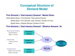
The Influence of Turbulence Model on Wake Structure of TSTs when used with a Coupled BEM-CFD Model. Ian Masters, R. Malki, Alison Williams & Nick Croft Marine Energy Research Group Swansea University. Modelling Approach. Moving Mesh Approach. Time-averaged Approach.

helena
Download Presentation

The Influence of Turbulence Model on Wake Structure of TSTs when used with a Coupled BEM-CFD Model

An Image/Link below is provided (as is) to download presentation Download Policy: Content on the Website is provided to you AS IS for your information and personal use and may not be sold / licensed / shared on other websites without getting consent from its author. Content is provided to you AS IS for your information and personal use only. Download presentation by click this link. While downloading, if for some reason you are not able to download a presentation, the publisher may have deleted the file from their server. During download, if you can't get a presentation, the file might be deleted by the publisher.

E N D

Presentation Transcript


  1. The Influence of Turbulence Model on Wake Structure of TSTs when used with a Coupled BEM-CFD Model Ian Masters, R. Malki, Alison Williams & Nick Croft Marine Energy Research Group Swansea University

  2. Modelling Approach Moving Mesh Approach Time-averaged Approach Source: A. Mason-Jones , PhD thesis Cardiff University (2010)

  3. Array Modelling

  4. Time-Averaged Influence of Blades

  5. Discretisation of Turbine Blades

  6. Discretisation of Turbine Blades (2)

  7. Impact of Blades on the Flow

  8. Impact of Blades on the Flow (2)

  9. Calculating Resultant Forces

  10. Resolving Forces

  11. Calculating Source Terms (BEMT)

  12. Substituting Source Terms (BEM-CFD)

  13. Substituting Source Terms (BEM-CFD)

  14. Model Domain 0.17m 1.54m 0.84m 0.5m 0.25m 0.17m 0.5m 0.84m 1.4m

  15. Rotor Modelling

  16. Wake Edge Parameters

  17. Wake Edge Characterisation

  18. 95% Wake Edges P95% P∞ PWAKE P∞

  19. Turbulence Models k-epsilon • Eddy viscosity from single length scale • Turbulent diffusion occurs only at specified scale RNG k-epsilon • Account for different scales of motion k-omega • Viscous sub-layer flows • Adverse pressure gradients and separating flows

  20. Turbulence Models Shear Stress Transport (SST) • k-ω near boundary • k-ε in free-stream • Adverse pressure gradients & separating flows Reynolds Stress Model (RSM) • Reynolds Stresses directly computed • Directional effects of Reynolds stress fields • More suitable for anisotropic turbulence

  21. Velocity

  22. Velocity

  23. Velocity

  24. Turbulence Intensity

  25. Turbulence Intensity

  26. Turbulence Intensity

  27. Turbulent Viscosity

  28. Lateral Shear

  29. Velocity ProfilesTSR = 4.0

  30. Velocity ProfilesTSR = 4.0 & 6.0

  31. TI ProfilesTSR = 4.0

  32. TI ProfilesTSR = 4.0 & 6.0

  33. Wake Diameter 95% Velocity TSR = 4.0

  34. Wake Diameter 95% Velocity TSR = 4.0 & 6.0

  35. Wake Diameter 95% TI TSR = 4.0

  36. Wake Diameter 95% TI TSR = 4.0 & 6.0

  37. Wake Diameter 95% dUdzTSR = 4.0

  38. Wake Diameter 95% dUdzTSR = 4.0 & 6.0

  39. Conclusions • Turbulence Models affect Hydrodynamics • Lack of Measured Data for Validation • Possibly better represent turbulence

  40. Rotor Source Terms

More Related