Download
1 / 43
540 likes | 903 Views
KP3213 CAD/CAM. Lecture 1 snap shot What books to buy Objective of Lecture 2 Lecture 2: Curve modeling Book review of week 2. Books. To Buy: CAD/CAM Principles and Application 2 nd edition by PN Rao Published by Mc Graw Hill

E N D
KP3213 CAD/CAM • Lecture 1 snap shot • What books to buy • Objective of Lecture 2 • Lecture 2: Curve modeling • Book review of week 2
Books • To Buy: CAD/CAM Principles and Application 2nd edition by PN Rao Published by Mc Graw Hill • For reference: Computer Aided Design and Manufacturing by Farid M.L. Amirouche Published by Prentice-Hall International • For reference: Principles of CAD/CAM/CAE systems By Kun Woo Lee Published by Addison Wesley
Objective • Introduction to CAD software and hardware • Abbreviation • Design methodology
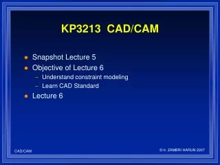
Lecture 1 snap shot • Multi-view Model • Wireframe Model • Solid Model • CAD/CAM Flow
Abbreviations in CAD • CAD – Computer Aided Design. The use of computer method to develop the geometric model of the product in 3D form such that the geometry and manufacturing requirement can be examined • CADD - Computer Aided Design and Drafting. Drafting added to generate the production drawings of the parts for the purpose of downstream processing • CAE – Computer Aided Engineering. The use of computer methods to support basic error checking, analysis, optimization, manufacturability etc of a product • CAM - Computer Aided Manufacturing. CNC transfer from CAD • CAPP – Computer Aided Process Planning. Use of computer for process plan • CATD – Computer Aided Tool Design. Design of jigs, dies etc. • CAP – Computer Aided Planning. Material requirement planning and Computer Aided Scheduling
Why CAM • Greater design freedom – changed incorporated during design stage • Increased productivity – totally organized by computer • Greater operating activity – flexible manufacturing method • Shorter lead time • Reduced maintenance • Reduce scrap and reworks • Better management control
Hardware • Basic components of a PC • Microprocessors/CPU for speeds (big project needs fast) e.g Intel latest processors • Memories e.g SDRAM • Graphics input devices e.g keyboard, mouse, joystick • Graphic display devices e.g Liquid Crystal Display (LCD), CRT, Plasma monitors • Graphics output devices e.g laser printers, color copier and plotter • Storage Devices e.g external drive, CD and DVD • Multi-user / server
Software • System software e.g Windows XP, LINUX • Programming language mostly use FORTRAN, now BASIC (Beginner’s all purpose Symbolic Instruction Codes) and C are used • Utilities – numerical procedures, matrix operations
Simple Curves • lines • circles • arcs • ellipses
Constructing Geometry with Simple Curves lines arcs circles
Freeform Curves • Representation needed for complex curves • Interpolate or approximate a set of points • Need to be controllable by the designer • Need to be computationally efficient and easy to store
Freeform Curves Open curve Closed curve
interpolated approximated Freeform Curves Control points
Representation of Curves • Conventional explicit and implicit forms have drawbacks • Example explicit form: • Example implicit form:
Drawbacks of Conventional Representations • They represent unbounded geometry • They may be multi-valued • Difficult to evaluate points along the curve • Depends on coordinate system
Parametric Representation • Curves are defined as a function of a single parameter:
u u v Parametric Representation Surface, P=P(u,v) Curve, P=P(u)
Parametric Cubic Polynomial Curves • Cubic polynomials are the lowest-order polynomials that can represent a non-planar curve • The curve can be defined by 4 boundary conditions
P1’ p1 p3 P0’ p1 p2 p0 Hermite Lagrange p0 Cubic Polynomials • Lagrange interpolation - 4 points • Hermite interpolation - 2 points, 2 slopes
Bezier Curves • Bezier curves were developed to allow more convenient manipulation of curves • A Bezier curve is a polynomial curve approximating a control polygon
Bezier Curve Control polygon
Bezier Curve Disadvantages • Difficult to interpolate points • Cannot locally modify a Bezier curve
2 1 3 4 Composite Curves • Curves can be represented by connected segments to form a composite curve • There must be continuity at the mid-points
Degrees of Continuity • Position continuity (endpoints connected) • Gradient or slope continuity (1st derivative) • Curvature continuity (2nd derivative) • Higher derivatives as necessary
Curve Continuity 2 1 3 Connected (C0 continuity)
Curve Continuity 1 2 Continuous tangent Tangent continuity (C1 continuity)
Curve Continuity 1 2 Continuous curvature Curvature continuity (C2 continuity)
2 1 3 4 Cubic polynomials Composite Curves • A cubic spline has C2 continuity at intermediate points • Cubic splines do not allow local control
B-spline Curves • B-splines are generalizations of Bezier curves • A major advantage is that they allow local control
Rational Curves and NURBS • Rational polynomials can represent both analytic and polynomial curves in a uniform way • Curves can be modified by changing the weighting of the control points • A commonly used form is the Non-Uniform Rational B-spline (NURBS)
Computer Graphics • Raster Scan Graphics • DDA Digital differential Analyzer) Algorithm, Y = mX + C • Coordinate System • World Coordinate System (WCS). Default. Actual coordinate system used as master for the component • User Coordinate System (UCS). Customized. • Database Structures for Graphic Modeling
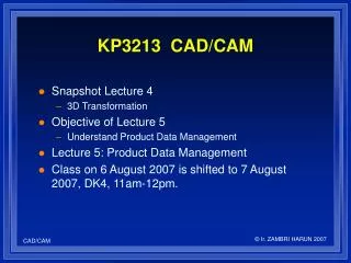
Transformation of Geometry • Translation (move in X or Y direction) • Scaling (magnification/reduction) • Reflection (mirror) • Rotation (angle)
Book Review for Week 2 • CAD/CAM Principles and Application 2nd edition by PN Rao Published by Mc Graw Hill • Chapter 2: 2.1 2.9 • Chapter 3: 3.1 3.4 • Chapter 4: 4.1 4.4