Download
1 / 47
470 likes | 643 Views
802.11 & VoIP. Allen Hollister Plantronics. Router. Router. Hol. Vo. lis. By. VoIP By Allen Hollister. VoIP By Allen Hollister. Router. Router. Router. Router. All. ter. en. IP. Router. Router. Trailer (4). Voice (10). RTP (12). UDP (8). IP (20). Ethernet (14).

E N D
802.11 & VoIP Allen Hollister Plantronics Allen Hollister, Plantronics
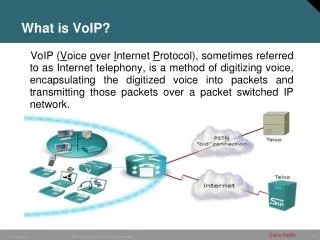
Router Router Hol Vo lis By VoIP By Allen Hollister VoIP By Allen Hollister Router Router Router Router All ter en IP Router Router Trailer (4) Voice (10) RTP (12) UDP (8) IP (20) Ethernet (14) Or 802.11 (34) Note: To view the animation, you need PowerPoint version 2002 or later Allen Hollister, Plantronics
Much of QoS comes down to making the system more “TDMA” like. We want packets moving along the same path at regular intervals Router Router VoIP By Allen Hollister VoIP By Allen Hollister Router Router Router IP Vo lis All Hol By ter en Router Router Router Trailer (4) Voice (10) RTP (12) UDP (8) IP (20) Ethernet (14) Or 802.11 (34) Allen Hollister, Plantronics
VoIP Layers Media (Voice) Plane Control/Signal Plane • VoIP sessions consist of three separate flows over the network • The outgoing media stream • The incoming media stream • The Signaling and Control stream. • Streams use different routes and they use different protocols. • Media Streams use RTP/UDP because voice data is very fragile. If it doesn’t get there within 150 msec, its useless! • Signaling and Control uses TCP because it is very important that the data arrive and be accurate. The time it arrives doesn’t matter so much. Allen Hollister, Plantronics
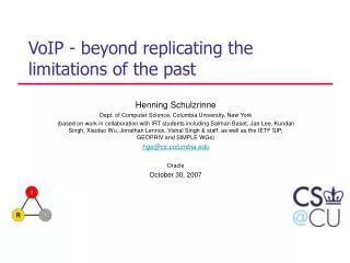
Ver IHL Type of Service Total Length (16 bits) Identifier Flags Fragment Offset Time to Live Protocol (6) Header Checksum Source Address Destination Address (Final destination address) Options and Padding Source Port Destination Port Sequence Number Acknowledgement Number Offset Reserved U A P R S F Window Checksum Urgent Pointer Options and Padding Connection-Oriented Protocol (TCP) Destination Address Destination Address continued (address of first router) Ethernet Ver .2 Header (14 bytes Source Address Source Address Continued Type IP Header (20 bytes) TCP Header (min length 20 octets) Data Data Link Trailer Variable length Data Link Trailer Allen Hollister, Plantronics
Source Port Destination Port Sequence Number Acknowledgement Number Offset Reserved U A P R S F Window Checksum Urgent Pointer Options and Padding TCP • A port specifies an application: for example port 23 specifies Telnet, while port 25 specifies e-mail. • A list of all assigned port numbers can be found at: http://www.iana.org/assignments/port-numbers • A combination of a port and an IP address is a “Socket” • Sequence number specifies the number assigned to the first byte of data in the current message. The first sequence number is random. The next sequence number will be the previous sequence number plus the number of octets in the last packet. It counts data octets! • Acknowledgement Number: Contains the sequence number of the next byte of data the sender of the packet expects to receive U-Urgent Data (Urgent Pointer field becomes active) A – ACK P – Push data needs to be promptly sent to recipient R – Reset – Abort session, error S – Syn F - Finish Allen Hollister, Plantronics
TCP Startup IP Host A IP Host B Synchronize Connection Synchronize: Sets sequence number randomly (ex 2000) Sync acknowledge from host B sets an acknowledgement number 1 greater than the original sequence number (ex 2001) then set its own random sequence number (ex 4000). Host A then send an acknowledgment number back of 1 plus the sequence number from host B (4001) Once data transmission is started, the sequence number is incremented by the number of data octets. For example if an initial sequence number is 100 and 150 octets of data are sent, then the next sequence number will be 250. Synchronize Acknowledge Acknowledge Data Transfer (Slow Start) Data Transfer Acknowledge (1) Data Transfer Acknowledge (2) Data Transfer Acknowledge (4) Disconnect Finish Finish Acknowledge Allen Hollister, Plantronics
Source Port Destination Port Length Checksum V P X CC M PT Sequence Number Time Stamp Synchronization Source Contributing Source (optional) Complete RTP Packet Destination Address Ethernet Ver .2 Header (14 bytes Destination Address continued Source Address Source Address Continued Type Ver IHL Type of Service Total Length Identifier Flags Fragment Offset IP Header (20 bytes) Time to Live Protocol(17) Header Checksum Source Address Destination Address Options and Padding UDP Header (8 bytes) RTP Header 12-16 bytes Voice Data – 40 msec G.729 is 40 bytes, G.711 320 bytes Data Link Trailer 4 bytes Data Link Trailer Allen Hollister, Plantronics
QoS in Packet Audio • Delay or Latency • Problem only with two way audio, not a problem for one way (broadcast) audio such as Real Networks. • Latency in excess of 300 msec round trip (150 msec one way) is not acceptable • People perceive latency as “rudeness” and it causes people to “step” on each other words. • Echo – TCLw is quite important! (TIA810a) • Echo is a problem for your listener. Typically, the person you are speaking with talks, his voice is heard in your receiver, some of that voice is then coupled to the microphone in your handset which is then transmitted back to the speaker but delayed by network latency. At certain amounts of delay and amplitude, it can make it almost impossible for the person to even speak. • Any round trip delay >28 msec requires echo canceling or very good TCLw! • VoIP always has a round trip delay >28 msec! • Lost Packets • More than 1% to 5% noticeable • Typical intranet <.1%, Internet <4% to 100% • Chief cause: Network congestion • Jitter – Variation in Delay • Typical: Intranet < 50 msec, internet <200 msec to ∞ • Chief Cause: Queuing, CSMA systems very unpredictable • Multiple paths through network causing some packets to arrive sooner than others. • If 802.11 VoIP phone can’t have predictable access to network, jitter is the result. • Adaptive jitter buffer solves jitter at expense of latency • Smart jitter buffers re-adapt during silence periods. • Audio quality – Vocoder issues, audio bandwidth • Various vocoder standards that allow for different audio bandwidths and different quality levels traded off against bandwidth. • G.711 64 Kbits/sec ADPCM 3 KHz bandwidth • G.729 8 Kbits/sec models voice in 10 msec chunks and sends DSP coefficients to reconstruct sound. • Others: See http://www.iana.org/assignments/rtp-parameters Allen Hollister, Plantronics
QoS - Delay • Delay > 150 msec one way is unacceptable • The old satellite overseas links had a one way latency of 500 ms • Typical intranet delay <50 msec, • Typical internet delay (best effort) <800 msec • Chief cause of network latency: • Queuing in Routers • Going from 100 Mbit/sec to < 1 Mbit/sec • Additional latency due to tradeoff of packet size vs. header overhead vs. power. • Header overhead doesn’t directly affect latency for high speed links (>1Mb/s) but does so indirectly in that more bandwidth is used. Coupled with other traffic, a congested network results that cause delay in accessing or result in lost packets. • 58 bytes (464 bits) of header overhead using wired Ethernet VoIP • Robust Header Compression (RHC) can reduce this to 20 bytes • 78 bytes (624 bits) using 802.11 wireless Ethernet of header overhead in VoIP • When power must be saved for battery life issues, the only solution is to increase the voice sample size from, for example, 10 msec to 40 msec, then pushing this accumulated data over a high speed link in something under 5 msec, and finally putting the device into a power save mode for 35 msec. • Increasing the voice sample size from 10 msec to 40 msec directly increases latency to 40 msec. You have to accumulate the entire set o samples before it can be packetized! • Jitter is converted to latency through the use of a “jitter buffer”. Data is accumulated in the jitter buffer for the maximum expected arrival time for the packet. This time adds directly to latency. • If one doesn’t wait for a long enough time, packets will be lost (but latency will be less) Allen Hollister, Plantronics
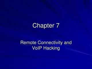
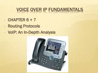
Latency – Daytime, Round Trip, Scotts Valley, CA – New York Round Trip Latency Scotts Valley to New York Max Min Average Daytime 534 125 143 Nighttime 325 115 118 Distance to NY 2582 miles. Round trip Transmission time in fiber for a 2582 mile distance is 44 ms (I assumed velocity of light is 117,000 miles/sec in fiber.) Allen Hollister, Plantronics
Round Trip Latency Distance from SF to London is 6052 miles – 103 ms transmission time round trip Distance from Scotts Valley to Moscow, 7362 miles, 124 msec transmission time round trip Allen Hollister, Plantronics
Round Trip Latency - 5 mile distance Allen Hollister, Plantronics
QoS Codec Standards • Codec Standards • G.711 • 64000 bits/sec (8000 samples/sec and 8 bits/sample) • ADPCM with either µ law or A law applied • A 20 msec audio sample requires 160 bytes • G.729 (Vocoder –Linear Predictive Coding) • 8000 bits/sec • Operates on 10 msec audio samples. A 20 msec audio sample would require two G.729 samples and a total of 20 bytes. • Other standards, G.729B, G.723.1, G.728, G.726, G.722 • Transcoding • While it is possible to transcode between standards, it is almost never a good idea. Audio quality is lost! • Transcoding also introduces latency Allen Hollister, Plantronics
Required Data Rate Allen Hollister, Plantronics
20ms, VP 78 byte 20ms, VP 78 byte 20ms, VP 78 byte 20ms, VP 78 byte 20ms, VP 78 byte 20ms, VP 78 byte VP VP VP VP VP VP 20ms Two VoIP Sessions Streaming Over A T1 Connection Router At T1 Speeds, 20 ms of G.729 (78 bytes) requires .404 ms of channel time for a single Voice Packet. At an 8 Kb/s sample rate for G.729, 20 ms of audio data results in 50 packets/sec being sent for a total of 20.2 ms of channel time. This is 2.02% of channel capacity. Allen Hollister, Plantronics
20ms, VP 78 byte 20ms, VP 78 byte 20ms, VP 78 byte VP VP VP DP 512 byte DP – 2.65 ms channel time 512 Byte Data Packet Arriving At Wrong Time Router At T1 Speeds, .4ms of channel time is required for Voice Packets 512 byte Data Packet (requiring 2.65 ms of channel time), collides with a VP. Queuing prevents the packet from being lost, but causes a time delay or “jitter”. Allen Hollister, Plantronics
20ms, VP 78 byte 20ms, VP 78 byte 20ms, VP 78 byte 20ms, VP 78 byte 20ms, VP 78 byte 20ms, VP 78 byte 20ms, VP 78 byte 20ms, VP 78 byte 20ms, VP 78 byte VP VP VP VP VP VP VP VP VP Congested Network Causing Packet Loss DP DP DP DP Router A VP collides with a another packet in a congested network. There is insufficient buffer space to prevent packet loss. Allen Hollister, Plantronics
20 ms voice packet, No other traffic 20 ms voice packet, Data Packet ahead of VP 22 ms of the 75 ms is transmission time PBX 1ms Switch routing 1 msec Coder, G.729 25 msec 78 byte voice packet .4 msec 2048 byte MTU data packet 2048 byte MTU Data packet 11 ms T1 uplink Estimated Latency T1 WAN uplink Wan/Lan 65 msec SF/NY T1 downlink 78 byte voice packet .4 msec PBX 1 ms Coder decompress 3 ms Jitter buffer 40 msec Switch routing 1 msec 2048 byte MTU Data packet 11 msec 137.8 msec one way latency 159.8 msec one way latency Allen Hollister, Plantronics
256 byte Data Packet Ahead Of VP No Other Traffic 22 ms of the 75 ms is transmission time PBX 1 ms Switch routing 1 msec Coder, G.729 25 msec 78 byte voice (20ms) packet 11 msec 256 byte MTU data packet 256 byte MTU Data packet 37 msec 56 Kbps uplink Estimated Latency 56 Kbps WAN uplink Wan/Lan 65 msec SF/NY 56 Kbps downlink 78 byte voice (20ms)packet 11 msec PBX 1ms Coder decompress 3 ms Jitter buffer 40 msec Switch routing 256 byte MTU Data packet 37 msec 159 msec one way latency 233 msec one way latency – Not Good! Allen Hollister, Plantronics
No Other Traffic, 11Mb/s 802.11 link 2048 Data Packet, 1Mb/s 802.11 link No other traffic, 1Mb/s 802.11 link If 2048 byte data packet remains in from of the voice packet, an additional 10ms delay occurs at the T1 uplink 118 byte RF uplink packet 802.11 RF Link .1 msec 1 msec Switch routing 1 msec 98 byte voice (40ms) packet .5 msec second 802 device grabs channel with 2048 byte packet 17ms 22 ms of the 75 ms is transmission time T1 Uplink 1.54 Mb/s Packetization delay & G.729 coding delay 45.5 msec Wan/Lan 65 msec SF/NY Estimated Latency 802.11, 40 ms VP Coder Decompress 5.5 ms 98 byte voice (40ms)packet .5 msec Switch routing 1msec Jitter buffer 80 msec 802.11 RF Link .1 msec 1 msec 218 msec one way latency 199 msec one way latency 201 msec one way latency Allen Hollister, Plantronics
Internet QoS standards • The external internet has developed a series of protocols and standards that when fully implemented, will allow telephony grade voice over the public internet. These include: • RSVP which guarantees bandwidth through all of the routers and prevents packet loss for voice packets (something else may lose packets if the network is bandwidth saturated, but it won’t be voice). • Diff-Serv uses the TOS (Type Of Service) field in the Internet Protocol (IP) to give priority over other data packets. This helps jitter and latency, two major areas of QoS concern. • MPLS (Multiprotocol Label Switching) makes a router look like a switch. The entire path for a particular voice session is reduced to the equivalent of one router “hop”. This again helps latency. • Recently the 1Gbit and now 10 Gbit Ethernet has become available. These technologies provide sufficient bandwidth as to enable very successful competition with telephony networks • These standards are relatively new and have not been fully rolled out. But when they are, then can make VoIP over the internet as good as a regular telephone connection. • These protocols are being used in private networks to provide high QoS for customers of these networks. Allen Hollister, Plantronics
RSVP Controls Queuing Session 1, guaranteed bandwidth Reserved Flow Scheduling Works in conjunction with WFQ Reserved queue for RSVP flow Queues serviced by weight VP1 VP1 Session 2: Guaranteed Bandwidth 100 byte voice packet Dequeue VP2 VP2 VP2 DP VP1 DP VP2 VP2 VP1 VP1 DP (Frag) DP (Frag) 200 byte data packet Classify Flow Specification: Source and destination address Protocol Session Identifier (port/socket) DP2 Discard!! Allen Hollister, Plantronics
Diff-Serv Router Highest priority Queue Reserved Flow Scheduling Works in conjunction with WFQ Queues serviced by weight VP2 VP1 Second highest priority Queue 100 byte voice packet Dequeue DP VP2 DP VP1 DP VP2 VP1 VP2 VP1 200 byte data packet Classify Flow Specification: Classify based on TOS field Allen Hollister, Plantronics
ToS - QoS Definitions Allen Hollister, Plantronics
Multiprotocol Label Switching - MPLS • MPLS adds a 32 bit header to the IP packet. It is used by routers to route once and switch many times • It is much faster to switch than to route. A core router may have 100,000 entries in its routing table • A predefined “tunnel” is created that each packet must follow. Each subsequent MPLS router reads the label and forwards it in “cut-through” mode. The router doesn’t have to read all of the IP headers, only those required to make the switch. • QoS is achieved by setting up high priority, high speed networks for high priority traffic and slower speed parallel networks for low or medium priority traffic. • AS far as the original packet is concerned, the routers carrying it through the MPLS network appear as a single hop. Allen Hollister, Plantronics
Signaling And Control • H.323 • ITU Standard Ver 1 released Jan 1996 Ver 2 released 1998 • Consists of other standards: • H.225 Call Signaling • Q.931 (ISDN Standard) • RAS (Registration, Admission, Status) • H.245 Control • Originally developed to provide conferencing based communication solutions for multimedia PC’s over LAN’s • It was not designed for IP solutions. Fixed in ver 2. • What it Does • Phase A – Call Setup • Phase B – Initial communication and capability exchange • Phase C – Establishment of audio/video communication • Phase D – Call Services • Phase E – Call termination • SIP • IETF Standard Released July 1999 • Does the same thing as H.323 • Seen as the “up and coming” protocol. Currently H.323 is more common because it has a 3 year head start. • MeGaCo (Media Gateway Control)/H.248 • Joint standard with IETF and ITU • Used to interface with the PSTN network • Works with H.323 and SIP • MGCP • Predecessor to Megaco • Proprietary Allen Hollister, Plantronics
SIP vs. H.323 Allen Hollister, Plantronics
H323 Terminal H323 Terminal Packet Network H323 MCU H323 Terminal H323 Gatekeeper H323 Gateway Objective Of H.323 Is To Enable The Exchange Of Media Streams Between H.323 Endpoints Scope of H.323 PSTN Allen Hollister, Plantronics
H.323 Stack H.323 Consists of a number of protocols. It specifies how these protocols will be used. • H.225 • Is itself a two part protocol. • 1) A variant of ITU-T recommendation Q.931, the ISDN layer 3 specification • Used for the establishment and teardown of connections between H.323 endpoints. • 2) RAS (Registration, Admission, & Status) • Used between endpoints and gatekeepers & enables the gatekeeper to manage the endpoints within its zone. • H.245 is used to manage media streams between session participants. • Ensures media streams sent by one participant can be received understood by another • Operates by establishing logical channels. These channels carry the media streams between endpoints. They have a number of properties • Media type • Bit Rate • etc Allen Hollister, Plantronics
RAS Functions • Gatekeeper Discovery • Enables an endpoint to determine which gatekeeper is available to control it • Registration • Endpoint registers with a particular gatekeeper. • Un-registration • Admission • Endpoint request to access network for purpose of participating in a session. • Bandwidth is specified as part of the request • Gatekeeper may turn down the request. • Bandwidth change • End point location • Gatekeeper translates an alias to a network address • Disengage • Status • Used by gatekeeper and endpoint to inform gatekeeper about call related status such as current bandwidth • Resource Availability • Used from gateway to gatekeeper in order to inform gatekeeper of the gateways currently available capacity, such as bandwidth. • Non-Standard • Allows proprietary information to be passed from endpoint to gatekeeper. Allen Hollister, Plantronics
Some Messages Supported By H.225 Q.931 • Alerting • Sent by called endpoint to indicate that the called user is being alerted. • Call Proceeding • Optional interim response sent by the called endpoint prior to sending the connect message • Connect • An indication that the called user has accepted a call • Setup • An initial message used to begin call establishment • Setup acknowledge • Optional response to setup. • Can be forwarded from a gateway in case of PSTN interworking • Release Complete • Used to bring a call to an end Allen Hollister, Plantronics
Session Initiation Protocol - SIP IETF • Performs Same Function As H.323 • WorldCom networks use SIP • ATT networks use H.323 • How “net heads” want to do telephony on packet networks • Very new standard • Because of head start, H.323 is more common now. • SIP is now being implemented in more new applications than H.323. Seen as “wave of the future” SIP (Session Initiation Protocol) SDP (Session Description Protocol) SAP (Session Announcement Protocol) RTSP (Real Time Streaming Protocol Allen Hollister, Plantronics
SIP Addressing • Addresses are known as SIP URLs (Uniform Resource Locators) • Take form of user@host which is similar to e-mail address (but they are different) • Syntax is sip:collins@home.net • Sip deals with multimedia sessions, which could include voice. • SIP can interwork with traditional circuit-switched networks. • SIP enables the user portion of the SIP address to be a telephone number • sip:3344556789@telco.net • Such an address could be used to cause routing of media to a gateway that interfaces with the PSTN • To clearly indicate the call is a telephone number, supplement the URL with: sip:3344556789@teleco.net;user=phone. Allen Hollister, Plantronics
SIP Network Entities • SIP defines two classes of network entities • Clients • An application program that sends SIP requests • A client might be a PC with a headset attachment or a SIP phone. • Clients can be in the same platform as a server. • SIP enable the use of proxies which can be either a client or server. • Servers • An entity that responds to those requests. • Four types of servers • Proxy Server • Redirect Server • User Agent Server • Registrar • SIP is a Client-server protocol. Allen Hollister, Plantronics
Servers Request Collins@work.com Proxy • A proxy server works like a proxy server used to access the internet from a corporate LAN • The client sends requests to the proxy and the proxy either handles the request itself or forwards it to other servers. • To those other servers, it appears as if the request is coming from the proxy rather than from the entity hidden behind the proxy. • Allows call forwarding/follow me services. Response Caller@work.com Request Collins@home.net Response Collins@home.net Allen Hollister, Plantronics
Redirect Servers Request Collins@work.com Redirect Server Caller@work.com • Redirect Server • Accepts SIP requests • Maps the destination address to zero or more new addresses • Returns the translated address to the originator of the request • Does not initiate any SIP requests of its own. Moved, contact Collins@home.net Ack Request Collins@home.net Response Collins@home.net Allen Hollister, Plantronics
Session Description Session Level Information Protocol Version Originator and Session ID Session Name Session Time Media Description1 Media Name And Transport Connection Information Media Description 2 Media Name And Transport Connection Information Session Description Structure Allen Hollister, Plantronics
SDP Syntax • Mandatory fields (test based) • v=(protocol version) • Also marks the start of a session description and the end of any previous session description. • o=(session origin or creator and session identifier) • s=(session name) • This field is a text string that could be displayed to potential session participants. • t=(time of session) • This field provides the start time and stop time for the session. • m=(media) • Indicates media type, the transport port to which the data should be sent, the transport protocol (e.g., RTP), and the media format (typically an RTP payload type. The appearance of this field also marks the boundary between session level-information and media-level information. Allen Hollister, Plantronics
SDP types - Optional • i=(session information) • u=(URI of description) – A web address • e=(e-mail address) - of person responsible for session • p=(phone number) - of person responsible for session • c=(connection information) • b=(bandwidth information) • r=(repeat times) • z=(time zone adjustment) • k=(encryption key) • a=(attributes) Allen Hollister, Plantronics
Some of the fields specified in SDP have sub fields. For example: Media Information (m) has four sub fields Media type Audio, Video, Application, Data, or Control Port Port number to which media should be sent Transport Formats Various types of media that can be supported In the case of several being supported, each is listed with the preferred sent first. Examples (Format) If a system wishes to receive voice on port 45678 and can handle speech that is coded according to G.711 mu-law, then RTP payload type 0 applies and: m=audio 45678 RTP/AVP 0 If a system wishes to receive voice on port 45678 and can handle speech that is coded according to any G.728 (payload type 15) GSM (payload type 3) or G.711 mu-law (payload type 0) and it prefers G.728 then: m=audio 45678 RTP/AVP 15 3 0 Subfields Allen Hollister, Plantronics
Example: Assume that Collins can support G.726, G.729, G.728, Boss can only support G.728. Note: Many SIP headers have been omitted for clarity. Invite sip:manager@work.com SIP/2.0 Cseq: 1 INVITE Content-Length:230 Content-Typeapplication/sdp v=0 o=collins 123456 001 IN IP4 Station1.work.com s=vacation i=Discussion about time off work c=IN IP4 station1.work.com t=0 0 m=audio 4444 RTP/AVP 2 4 15 a=rtpmap 2 G726-32/8000 a=rtpmap 4 G723/8000 a=rtpmap 15 G728/8000 SIP/2.0 200 OK Cseq: 1 INVITE Content-Length:161 Content-Typeapplication/sdp v=0 o=manager 45678 001 IN IP4 Station2.work.com s=Company vacation policy c=IN IP4 station2.work.com t=0 0 m=audio 6666 RTP/AVP 15 a=rtpmap 15 G728/8000 ACK sip:manager@work.com SIP/2.0 CSeq:1 ACK Content-Length: 0 Conversation Allen Hollister, Plantronics
SIP Interworking With PSTN & H.323 • PSTN Interworking • Requires a “Network Gateway” (NGW) for control interworking. • NWG interfaces with SS7 database though ISUP protocol. • Translates control and signaling between the two different networks. • Requires a Media Gateway to convert media between the two different networks • H.323 interworking • Internet draft titled “Interworking between a SIP/SDP network and H.323” has been created. • Requires the use of a gateway that looks like a SIP user agent client or user agent server on the SIP side. On the SIP side it might include a Sip registrar function and/or proxy function. • On the H.323 side of the gateway, it could contain a gatekeeper function. • Translation between all of the H.323 messages and SIP messages occurs in this Gateway. Allen Hollister, Plantronics
802.11 and VoIP at the Physical & Link Layers • 802.11e has gone a long way to making VoIP compatible with 802.11. • Many VoIP products are battery operated. • Power management in 802.11e is very important • EDCF and HCF are critical for good QoS • Create consistent access to the network providing low jitter, and low latency • The sidelink capability is quite helpful • Can be used to save power • Can be used to talk to another device (PDA remote dialer for example) while still having contact with the AP. • The PDA does the signaling and call setup, the VoIP handset handles the media. • Diff-Serv at the layer 2 is a good approximation to 802.11e. • We should work with the people who are applying Diff-Serv in the routers to make sure that the standards don’t clash • At the physical and link layers (given the ratification of 802.11e) we have to make sure that we don’t define something that would prohibit the use of VoIP. • Example: Someone suggested in the HTG that we could get more (payload) bits/sec by forcing a minimum size payload packet of maybe 2 to 4 KB. Doing so, would make VoIP impossible as the latency would go out of sight. • The codec standard, G.729, can code 10 msec of audio in 10 bytes. Thus 2000 bytes would code 2 seconds worth of voice. The minimum latency would then be 2 sec. This is quite a bit over the 150 msec limit!!! • If the committee wants to do this, they should do so with the understanding that this would be a knock-out for VoIP • Of course, for those companies that really want to do this, there will be workarounds. Get ready for a new codec standard that has 10 bytes of audio and 1990 bytes of padding • Get bit rate up by creating a Robust Header Compression standard Allen Hollister, Plantronics
VoIP and 802.11 At Layers Above The Link Layer • Typically, 802 does not address layers above the link layer, but I understand this is more by convention than rule. • If we chose to do so in this case, we would find: • Most of VoIP is already very well covered by standards at these levels. • However, the signaling standards, while complete in themselves, are not currently compatible with each other. SIP can’t talk to H.323 without a gateway! • It might be fair to pick a signaling standard as “the” standard for use on 802.11 products. • This would ensure that any 802.11 VoIP phone could talk with any other 802.11 phone, but: • It would put us in the middle of “wars” about this issue • Its unlikely that the members of this committee could agree as I suspect many are on one or the other side of this issue. • Some thought could be given to selecting a codec or set of codec’s as standard. This needs caution. • All of the signaling standards have a very good mechanism for negotiating which codec to use. • Selecting only one would stifle innovation and prevent growth, but: • Selecting a few that all must support would ensure that communication could at least be established. • In this case, it would be very important to not prohibit other codec's from being used. • Finally, creating some good ways to do fast, seamless, handoffs as the VoIP 802.11 phone wanders around a building would be a good idea. • Coordinate with the IETF and other organizations who are creating a lot of new standards in this area to ensure that we remain compatible • Security is likely to be a big issue for this technology. The 802.11i group has gone a long way to solving this problem, but: • It is likely in the not too distant future that complete VPN capability will become part of the operating system for portable devices. • We Should track this, and make sure that we remain compatible. Allen Hollister, Plantronics
What Can The Chip Manufacturers Do? • Get the power down! • Support the 802.11e standard • If you believe the PSTN system will be around for awhile, then support HCF. • HCF is not necessary if you not using the PSTN system. If you are, then it makes life easier for the telephone systems people since that entire network runs from a central clock. • Support the 802.11i standard. Allen Hollister, Plantronics
Thank you Allen Hollister, Plantronics