Download
1 / 10
100 likes | 235 Views
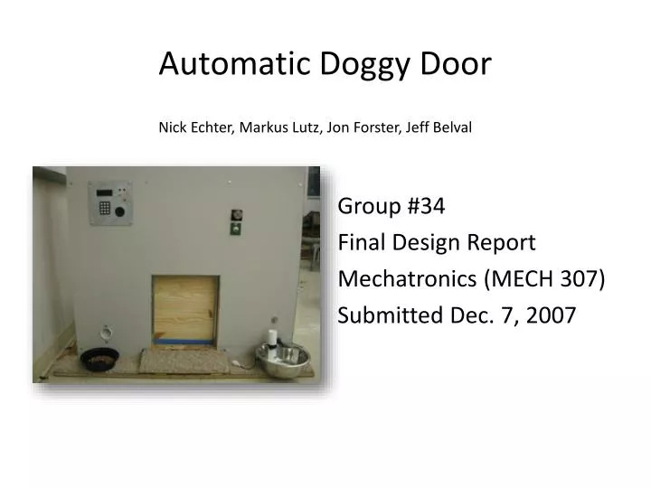
Automatic Doggy Door. Group #34 Final Design Report Mechatronics (MECH 307) Submitted Dec. 7, 2007. Nick Echter, Markus Lutz, Jon Forster, Jeff Belval. Photographs and Figures of Final Design. Total Assembly.

E N D
Automatic Doggy Door Group #34 Final Design Report Mechatronics (MECH 307) Submitted Dec. 7, 2007 Nick Echter, Markus Lutz, Jon Forster, Jeff Belval
Total Assembly Front View Back View door motor/counter weight system user interface with keypad, speaker, and LCD IR receiver hood on/off solenoid valve switch Fig. 1 Fig. 2 water dispenser and float valve assembly watering system with reservoir and solenoid valve food dispensing system with food dispenser and stepper motor food outlet doggy door and exposed floor switch
Food and Water Outlets(At the Front of the Assembly) Float switch housing (float switch is located within) water line from reservoir Food Outlet Fig. 4 Float switch Fig. 3 Fig. 5
Detailed View of Insides water reservoir 12 V DC door motor back of user interface potentiometer voltage regulator main PIC on/off solenoid switch EDE 702 Stepper motor chip sound chip voltage regulator stepper motor solenoid valve housing for relay switch Fig. 6 Fig. 7 counter weight and guiding track food dispenser Power supply for motor, valve and circuitry
Close Up View of Circuit Housing LED LCD microphone for sound recorder potentiometer main PIC push button activator for sound recorder sound projector EDE 702 sound chip voltage regulator Stepper motor chip Fig. 8 stepper motor
IR Sensor and Motor Control System LMD 18200 H bridge top view Fig. 10 infrared sensors mounted above glass (viewed from below) Fig. 9 infrared sensors Motor control PIC with inputs from the top, step, and floor switches; and IR sensors Fig. 11 infrared output LED’s worn on dog collar
Food Dispenser Fig. 12 Fig. 13 funnel guides food into valve housing valve rotated by stepper motor Pushes the food out the bottom hole total assembly Fig. 14
Door Motor Control Switches Fig. 16 Face Plate sound input LED Potentiometer (for display contrast) recording activator switch floor switch top switch step switch Fig. 15 LCD keypad speaker Fig. 18 Fig. 17