Download
1 / 33
350 likes | 649 Views
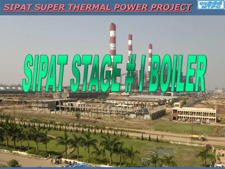
SIPAT SUPER THERMAL POWER PROJECT. SIPAT STAGE # I BOILER. SIPAT STAGE # 1 BOILER. ECO. O/L LINKS. ECONOMISER TO 1 ST PASS TOP HEADERS :. OUTLET HEADERS. ECO O/L HDR. VERTICAL WALL. INTERMITTENT HEADERS. ECO. JUNTION HEADERS. ECO. MIXING PIECE. SPIRAL WALL. ECONOMISER.

E N D
SIPAT SUPER THERMAL POWER PROJECT SIPAT STAGE # I BOILER
ECO. O/L LINKS ECONOMISER TO 1 ST PASS TOP HEADERS : OUTLET HEADERS ECO O/L HDR VERTICAL WALL INTERMITTENT HEADERS ECO. JUNTION HEADERS ECO. MIXING PIECE SPIRAL WALL ECONOMISER BOTTOM RING HEADER ECO I/L HDR
ECONOMISER : COUNTER FLOW4 BANKS163 ASSEMBLIES4 JUNCTION HEADERS224 HANGER TUBESECO OUTLET HEADERSA 106 C ; SA 210 C SPIRAL AND VERTICAL WALLS : TOTAL SPIRAL TUBES : 440 (102X2 FRONT & REAR; 108X2 LEFT & RIGHT)SPIRAL TO VERTICAL RATIO = 1:3FRONT VERTICAL TUBES: 336SIDE WALL TUBES: 648REAR SCREEN TUBES : 280REAR HANGER TUBES : 56TUBES : T22HEADERS : P12
START UP SYSTEM : SEPERATORS I/L LINKS 1ST PASS ROOF O/L HEADERS SEPERATOR TANKS STORAGE TANK STORAGE TANK WR WR ZR ZR BCP BCP MIXING PIECE MIXING PIECE TO ECONOMISER TO ECONOMISER FLASH TANK FLASH TANK UG UG CONDENSER CONDENSER FEED WATER LINE FEED WATER LINE BOILER FILL LINE BOILER FILL LINE
2ND PASS STEAM FLOW : EXTENDED WALL : BACK PASS ROOF I/L HDR 1ST PASS ROOF I/L HDR BACK PASS TOP LHS HDR BACK PASS TOP RHS HDR EXTENDED WALL EXTENDED WALL HDR BACK PASS BOTTOM RING HDR
BACK PASS WALLS & HEADERS : EXTENDED WALL : FURNACE FRONT ROOF : 168 BACK PASS ROOF : 111 BACK PASS REAR WALL : 111 BACK PASS SIDE WALL : 328 BACK PASS FRONT WALL : 167 BACK PASS SCREEN : 167 TUBES : T12 HEADERS : P12 EXTENDED WALL FLOOR : 142 EXTENDED SIDE WALL : 142 TUBES : T12 HEADERS : P12 FLUID COOLED SPACER TUBES: 3 BACK PASS WALLS & HEADERS : START UP SYSTEM : LINK PIPES : P12 SEPERATORS & STORAGE TANK : SA 302C LINK PIPES : P12 SEPERATORS & STORAGE TANK : SA 302C
DIVISIONAL PANEL : II ND PASS TOP RHS HDR DIV. PANEL I/L HDR FROM II nd PASS BOTTOM RING RHS HDR DIV. PANEL O/L HDR DIV. PANEL O/L HDR DIV. PANEL I/L HDR II ND PASS TOP LHS HDR FROM II nd PASS BOTTOM RING LHS HDR SH DIV. PANEL TUBES : 480 TUBES : T23; T91 HEADERS : P12; P23 FLUID COOLED SPACER TUBES : 6 DIV. PANEL DIV. PANEL
PLATEN AND FINAL SH : PLATEN TO FINAL SH LINK DIV. PANEL TO PLATEN LINK TO HP TURBINE PLATEN O/L HDR PLATEN I/L HDR FINAL SH O/L HEADERS DIV. PANEL I/L HDR FINAL SH I/L HDR DIV. PANEL O/L HDR DIV. PANEL O/L HDR DIV. PANEL I/L HDR PLATEN ASSEMBLIES : 20 NO OF TUBES : 480 TUBES : T12; T23; T91 HEADERS : P12; P23 PLATEN COILS FINAL SH COILS COUNTER FLOW DIRECTION NO OF STAGES : 2 ASSMBLIES : 2X55 NO OF TUBES : 935 TUBES : T23; T91 HEADERS : P23; P91
TO IPT REHEATERS : LTRH O/L TO FINAL RH I/L LINKS LTRH O/L HDR FINAL RH I/L HDR FINAL RH O/L HDRS NO OF BANKS : 3 NO OF TUBES : 111 TUBES : SA 210C; T12; T23 HEADERS : SA 106C; P12 TO IPT LTRH BANKS FINAL RH FROM CRH NO OF ASSEMBLIES : 41 NO OF TUBES : 615 TUBES : T23; T91; SUPER 304H HEADERS : P12; P91 LTRH I/L HDR FROM CRH
540°C, 255 Ksc 568°C, 47 Ksc 492°C, 260 Ksc 457°C, 49 Ksc FUR ROOF I/L HDR ECO HGR O/L HDR HRH LINE MS LINE 411°C, 277Ksc 411°C, 275 Ksc SEPARATOR STORAGE TANK FINAL SH FINAL RH LTRH DIV PANELS SH PLATEN SH VERTICAL WW G ECO JUNCTION HDR LPT IPT LPT 305°C, 49 Ksc CONDENSER HPT ECONOMISER ECO I/L Spiral water walls FEEDWATER BWRP 290°C, 302 KSC FUR LOWER HDR FRS
FEED WATER PUMP WATER WALL/ EVAPORATOR WATER WALL/ EVAPORATOR SUPERHEATER SUPERHEATER ECONOMISER ECONOMISER SEPERATOR SEPERATOR RECIRCULATION PUMP STORAGE TANK FEED WATER PUMP FEATURES OF SUPER CRITICAL BOILER : 1. ONCE THROUGH OPERATION : CONSTANT WATER WALL FLOW(below 30% load) ONCE THROUGH FLOW OPERATION (above 30% load)
2. CONSTANT PRESSURE OPERATION : Above 90% & below 30% 3. SLIDING PRESSURE OPERATION : B/W 30% & 90%
ADVANTAGES OF SLIDING PRESSURE OPERATION • 1. No additional pressure loss between boiler and turbine • 2. Low Boiler Pr. at low loads • - Less fatigue of Pr. part components • - Longer life of all components, Less wear of components • - Less Maintenance • 3. Lower thermal stresses in the turbine during load changes • 4. Control range of RH temp is extended • 5. Overall reduction in power consumption and improved heat rate
MS Line HT CRH Line HT HRH Line HT SG ECW SYSTEM MS Line Welding Completion CRH Line Welding Completion HRH Line Welding Completion ID FAN # 1A TRIAL RUN FD FAN # 1A TRIAL RUN MS Line Hanger Erection Cold Setting CRH Line hangers Cold Setting HRH Line Hangers Cold Setting SAPH # 1A TRIAL RUN MS Line Insulation CRH Line Insulation HRH Line Insulation BRP TRIAL RUN SACNNER AIR SYSTEM READINESS Temporary Piping Completion FURNACE READINESS FUEL OIL SYSTEM READINESS Boiler Light Up & Steam Blowing CHEMICAL CLEANING OF BOILER AUX PRDS READINESS ACW System COMPRESSED AIR SYSTEM READINESS MDBFP Trial CW SYSTEM READINESS GATES, DAMPERS / VALVES TG : SG : CEP Trial MFT CHECKING TG ECW System HOT Well Readiness DDCMIS FSSS READINESS
LIST OF APPROVED PROCEDURES Boiler Commissioning is carried out based on the guide lines of Corporate commissionin groups. OS) These are the list of approved commissioning procedures which are followed in sipat commissioning activities 1. BOILER HYDRO TEST 2. OIL FLUSHING OF ROTARY MACHINES 3. BOILER & DUCTS AIR TIGHTNESS TEST (ATT) 4. ESP AIR IN LEAK TEST 5. ESP GAS DISTRIBUTION (GD) TEST 6. BOILER CHEMICAL CLEANING 7. BOILER COLD AIR VELOCITY TEST 8. CLEAN AIR FLOW TEST 9. LDO & HFO SYSTEMS COMMISSIONING 10. BOILER & AUX LINES STEAM BLOWING
COMMISSIONING MILE STONES • BOILER HYDRO TEST : • HP SYSTEM : Hydro test done on 20.12.2006 • HP system hydro test is done at 410 KSC. HP system consists of Economiser, boiler 1st & 2nd pass, divisional panel, platen & final super heater upto boiler stop valves. • MP SYSTEM : Hydro test done on 26.03.2008 • MP system hydro test is done at 80.1 KSC. MP system consists of CRH isolator to LTRH, Final Reheater upto HRH isolators. • 2.BURNER TILT, OIL GUNS & IGNITOR CHECKING : • Checking is completed on 24.12.2007 • Burner tilt checking is done from inside the boiler in which burner limits +300 & - 300 angles adjusted. Oil guns & ignitors clearances are checked inside the boiler. • 3.FD, ID & PA FANS COMMISSIONING : • FD Fan # 1A trial run taken on 03.03.2010 ID Fan # 1A trial run taken 15.03.2010 PA Fan # 1A trial run taken 18.03.2010
COMMISSIONING MILE STONES • 3.FD, ID & PA FANS COMMISSIONING : • FD Fan # 1B trial run taken on 22.06.2010 ID Fan # 1B trial run taken 21.06.2010 PA Fan # 1B trial run taken 22.06.2010 • Fans commissioning involves following steps: • Lube oil flushing of lube oil skid, lube oil lines with flushing oil (32 grade) (bearings bypassed) (Completion criterion is Moisture & Mechanical impurities should be below 100 ppm) • Lube oil flushing through bearings (32 grade) • Lube oil flushing through bearings (68 grade oil) • Blade pitch commissioning & discharge gate commng. • Cooling water lines flushing & charging • Fan trial 4.AIR PREHEATERS COMMISSIONING : • SAPH # 1A trial run taken on 27.03.2010 • SAPH # 1B trial run taken on 20.04.2010
4.AIR PREHEATERS COMMISSIONING : • PAPH # 1A trial run taken on 29.03.2010 • PAPH # 1B trial run taken on 20.04.2010 • Air Preheaters commissioning involves following steps: • Lube oil motors & main motor no load trial • Lube oil flushing of Support & Guide bearings with 32 oil (Completion criterion is Moisture & Mechanical impurities should be below 100 ppm) • Lube oil flushing through bearings (32 grade) • Lube oil flushing through bearings (680 grade oil) • Air motor service air line blowing • Cooling water lines flushing & charging • Air preheater trial with air motor & electrical motor
4.BOILER & DUCT ATT : • Secondary air duct ATT is completed on 01.04.2010 Primary air duct ATT is completed on 05.05.2010 Flue gas air duct ATT is completed on 24.04.2010 Furnace ATT completed on • ATT of boiler & ducts is done at 150 mm of water column. • Secondary air duct & boiler pressurisation is done by FD Fan. • Primary air duct pressurisation is done by PA fan. • Flue gas duct pressurisation is done by using temporary blowers • 5.ESP COMMISSIONING : • ESP Air In Leak test: All passes air in leak test completed on 09.11.2008 • The test is done to prove that air in leak into ESP is with in guaranteed value of 1% of design gas flow rate. • ESP Rapping system commng. : All passes rapping systems commng. completed on 21.07.2010 • Each Pass has 18 nos. collecting electrodes rapping system, 18 nos emitting electrode rapping system & 2 nos. gas distribution plates rapping system.
5.ESP COMMISSIONING : • ESP Fields charging • ESP GD test completed on 25.08.2010 • This is done to verify uniform flow distribution inside the ESP Chambers. • 6.BOILER CAVT : • CAVT (Cold Air Velocity Test) is completed on 03.09.2010 • This test is done to check flue gas flow patterns inside the boiler. • 7.AIR BALANCE TEST (ABT): • 8.BOILER CHEMICAL CLEANING : • Boiler Chemical cleaning is completed on 30.09.2010 Chemical cleaning involves following steps: • Flushing • Acid Cleaning • Rinsing • Pre Neutralization • Neutralization • Passivation
Main chemicals used are formic acid (10%), sorbic acid, coronil 200S • Boiler chemical cleaning is completed in 7 days. • 9.BRP (Boiler Recirculation Pump) COMMISSIONING : • BRP trial completed on 13.10.2010 • BRP commissioning involves following steps: • Cavity filling line flushing (until Conductivity & Turbidity reaches required parameters) • Flushing through motor cavity & through cooler • ECW lines water flushing • Pump trial • 10.BOILER LIGHT UP : • Boiler is Lighted Up on 27.10.10 • Boiler is lighted up with LDO and all 4 corner oil guns were proven. • 11.STEAM BLOWING : It has following steps • PRE STEP1: • Separator Superheater Main Steam Line Main Stop Valve • Temporary Piping Temporary MOV Tailpipe to atmosphere • Blowing is done from 40 KSC to 20 KSC
11.STEAM BLOWING : Steam blowing consists of following steps: PRE STEP 2: Separator Superheater Main Steam Line HP Bypass Valve Cold RH line backward flush through drain pot near RH inlet header Temporary Piping tailpipe to atmosphere Blowing is done from 40 KSC to 20 KSC MAIN STEP 1: Separator Superheater Main Steam Line Main Stop Valve Temporary Piping Temporary MOV Non-return Valve Cold Reheat Line Reheater Hot Reheat Line IPT Stop Valve Tailpipe to atmosphere Blowing is done from 80 KSC to 40 KSC MAIN STEP 2: Separator Superheater Main Steam Line Main Stop Valve Temporary Piping Temporary MOV Non-return Valve Cold Reheat Line Reheater Hot Reheat Line LP Bypass Valve Tailpipe to atmosphere Blowing is done from 80 KSC to 40 KSC
PF SYSTEM COMMISSIONING: (a) Seal air fan & its dampers (b) Mills commissioning: • Lube oil pumps load trial • Lube oil flushing of oil line with 32 oil bypassing gear box & bearings (Completion criterion is Moisture & Mechanical impurities should be below 100 ppm) • Lube oil flushing through bearings & gear box(32 grade) • Lube oil flushing through bearings (320 grade oil) • Cooling water lines flushing & charging • Roller & Bowl gap adjustment • Spring tension adjustment • P&I checks & Mill solo run.
PF SYSTEM COMMISSIONING: (C) RC Feeders • Motor checks • P&I checking • Feeder belt trial with clean out conveyor. • Commissioning of gates & dampers • Commng of HAD, CAD, HAG, CAG, BIG, MDV from remote (E) Clean air flow test of mills as per approved procedure
Provision of manholes in ducts & hoppers • Oil gun cleaning system • BRP fill line from boiler fill pump • FD, ID & PA fans blade pitch local indication • Black Start Up line in unit # 1 • Additional vents are provided in SGECW system • Boiler headers & links replacement
BOILER HEADERS REPLACEMENTS • Some of the super heater headers were replaced with higher grade materials. • 5 nos. of headers & link pipes of Gr P23 were replaced with Gr P91. • This material replacement is done to avoid probable material failure in the pipes and fittings of the boiler subjected to very high temperature and pressures.