Download
1 / 20
200 likes | 296 Views
Integrating UML Activity Diagrams with Temporal Logic Expressions. João Araújo & Ana Moreira CITI - FCT/Universidade Nova de Lisboa {ja|amm}@di.fct.unl.pt EMMSAD 2005 Porto, Portugal 13-14 June 2005. Contents. Motivation Formal specifications Temporal logic Transformation rules

E N D
Integrating UML Activity Diagrams with Temporal Logic Expressions João Araújo & Ana Moreira CITI - FCT/Universidade Nova de Lisboa {ja|amm}@di.fct.unl.pt EMMSAD 2005 Porto, Portugal 13-14 June 2005
Contents • Motivation • Formal specifications • Temporal logic • Transformation rules • Applying the approach to a case study • Conclusions
The aim here is to obtain a formal specification from activity diagrams Motivation • Activity diagrams are a powerful technique to describe requirements in use cases • However, this is not enough to guarantee that the requirements do not contain errors, ambiguities, omissions and inconsistencies • These drawbacks can only be identified and corrected early in the development process if formal description techniques are used
Formal specifications • Formal specifications help to reason about the system earlier • Detection of omissions, ambiguities, inconsistencies • Feedback to the requirements capture • Rules bridge the gap between a set of informal requirements and a formal specification
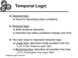
Temporal Logic (1) • Temporal logic can specify progress issues by showing how the various activities interact • for example, when specifying the priority, or the order in which activities may happen • Activity diagrams show the flow of control from activity to activity, which can naturally be expressed with temporal logic • where activity and action states are our properties
Temporal Logic (2) • The resulting temporal logic expressions could be used to validate requirements against the users by means of animation techniques • There is some work on programming languages based on the execution of temporal logic • That could be used to implement the specs obtained using our transformation algorithm • Tokio, METATEM and FTLL
Temporal Logic (3) • The temporal logic operators used are o (always) and à (eventually). • The main program properties are (Manna & Pnuelli): Safety property: op Guarantee property: àp Response property: o(p àq)
Transformation Rules (1) • A simple transition, in an activity diagram, from an action or an activity stateaito another action or activity stateai+1, can be formalised as (aiai+1)
Transformation Rules (2) • In the case of a sequential transition: • if there is only one action or activity state oàai,where i = 1; otherwise • if there is a sequence of states, o(aiàb), whereairepresents the first action or activity state andbthe rest of the sequence. bhas two forms: • aj with 1 < j £ n, to deal with the last action or activity state • aj à (aj+1 … à (a n-1 à a n)…) where 1<j £ n
Transformation Rules (3) • In case of branching, we have associated conditions (condition k, condition k+1, …, conditionk+n) to the transitions. Therefore we have the expression • (conditionkaiàai+1) condition k+1 aiàai+2, … condition k+naiàak+n+1 where 1 £ i £ n and 1 £ k £ n
Transformation Rules (4) • When we have a fork: • if there is a transition from an action or activity state ai to a group of concurrent action or activity states gk (represented by a fork): • ai àgk, where gk= np=i+1ap, where is the conjunction of all the activity states ai
Transformation Rules (5) • if we have a group of concurrent action or activity states gk, being joined and transited to an action or activity state aj • gkà aj, where gk is as before (step 4) , and j > p, i +1 < p < n
The Example • A customer should be able to register in the system • This registration results in opening an account for him that will be administrated by an Accounting System • S/he can buy a product whose shipping is realized by a Shipping Company • The Accounting System captures the order • The customer can also cancel an order, or return the product • As a consequence, these services have the effect of updating the customer’s account
TL Expression for Process Order o (requestProduct à (processOrder à (pullMaterials à (shipOrder à ((receiveOrder billCustomer) à (payBill à (closeOrder)))))))
Incremental Specification • Our approach could be used to build incrementally a complete formal specification of the system • or at the least the critical parts of the system, where all the temporal logic expressions should be composed • In such a scenario, validation would be realized incrementally
Conclusions • Synergetic approach • Encouragement of formalisation at early stages • identify omissions and ambiguities in the requirements • early feedback to the requirements capture • more precise and better quality systems • Normalisation of different notations into a mathematical notation • Promotes deep reasoning about the system • The results can be useful to the MDA community as our formalizations are, in fact, model transformations
Future work • To use the approach to generate prototypes in order to validate requirements together with the stakeholders • Investigate the expected evolution of the resulting specification into a process that builds a specification centred on objects • Reverse engineering should be defined, i.e., from TL formulas we should obtain the AD automatically • Investigate how our approach can be extended to contemplate Petri nets features • Apply the approach to real case studies