Download
1 / 17
170 likes | 500 Views
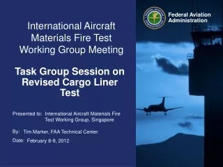
International Aircraft Materials Fire Test Working Group Meeting. Test Results for Proposed Cargo Liner Advisory Circular Material. International Aircraft Materials Fire Test Working Group. Tim Salter, FAA Technical Center. June 25-26, 2014, Solothurn, Switzerland. Last Meeting.

E N D
International Aircraft Materials Fire Test Working Group Meeting Test Resultsfor Proposed Cargo Liner Advisory Circular Material International Aircraft Materials Fire Test Working Group Tim Salter, FAA Technical Center June 25-26, 2014, Solothurn, Switzerland
Last Meeting • Proposed guidance submitted by the Cargo Liner AC Task Group is currently under review • Some of the items proposed by the task group, as well as items to be added by the FAA, needed to be tested before they were proven to be acceptable for implementation into an Advisory Circular
Items Tested • Backside Burning • Define acceptable time and/or temperature during backside burning of a test material • Fastener Pitch • Test proposed maximum safe fastener spacing for standard liner joint configurations • NexGen Burner Calibration • Define thermocouple configuration and calibration temperatures • Exhaust Flow • Determine allowable minimum/maximum exhaust airflow rates in test chamber
Backside Burning • From the Handbook: • “Occasionally, the back face ignition is due to the test flame wrapping around the sample holder, directly igniting backside outgasses. This is not considered a failure, but may void the test.” • Ran multiple tests using a woven epoxy, as well as sandwich panels which are known to both be materials capable of passing the cargo liner test criteria • Ignite outgassing using an electric igniters located above the liner material • Observed the amount of time required for the back side burning to self extinguish, as well as the location of the flame on the material • Determine if a time limit is required for self extinguishment, or material can be considered a failure based only on exceeding the 400°F failure criteria
Backside Burning • During testing, the liner material releases an epoxy vapor, which can sometimes ignite and cause a flame to appear on the side of the material facing away from the burner flame • This situation is less likely to occur on an aircraft, but can bring up questions during liner testing • Igniters and an additional thermocouple were added (for this study only) to the standard test rig to induce backside burning and help more closely examine the issue
Backside Burning • Burning on the back face of the liner material often occurs around the out perimeter of the sample, near the metal sample holder, and away from the thermocouple positioned near the center of the sample • The addition of another thermocouple located nearer to the flame on the back face of the sample showed the that temperatures measured four inches above the woven/epoxy material did not exceed 400º F
Backside Burning • Sandwich panels often outgas through the edges of their core • When ignited, these flames were shown to exceed 1400º F for a period of a few seconds, and may stay above 400º F for 2-3 minutes or more during testing • Currently working on a final ruling regarding backside burning and how it relates to pass/fail criteria, can be discussed in task group
Fastener Pitch • The guidance material has proposed that the following joint configurations require no testing: • Overlap joint of laminate liners with a 1” or greater overlap, and 4” or less spacing between fireproof fasteners when the liners pass the oil burner Material Only Test. (This test exclusion does not apply to sandwich panels.) • Overlap joint of laminate liners with a metallic support on the backside of the joint and 1” or greater overlap, and 9” or less spacing between fireproof fasteners.The liners pass the oil burner Material Only Test and metallic support is at least 1” wide and 0.04” thick. Support
Fastener Pitch • Constructed samples based on description of standard joint as described in the guidance material • Joints were constructed from a heavy woven “Conolite” material (0.033” thickness), as well as a thinner Tedlar coated liner (0.013” thickness) in order to determine, if any, the effect of cargo liner thickness on fastener pitch • Steel bolts and nutplates provided by Zodiac were used to assemble the joints • The metallic support will be constructed from 0.04” thickness 2024 aluminum alloy in the shape of an “L” bracket • Samples will be tested to ensure no flame penetration and temperatures measured 4 inches above the center of the panel remain under 400°F
Fastener Pitch Hardware Bolt and Washer Nutplate with Rivets
Conolite Samples Joint Sample, 4” Pitch Spacing Joint Sample w/Bracket, 9” Pitch Spacing
Tedlar Coated Samples Joint Sample, 4” Pitch Spacing Joint Sample w/Bracket, 9” Pitch Spacing
Fastener Pitch Test Results • 2 samples of each configuration were tested for a total of 8 tests • Temperatures measured 4 inches above the samples did not exceed 300ºF for any of the tests (100ºF below the 400ºF failure criteria) • Flame penetration did not occur for any of the samples tested • Proposed guidance material is acceptable
NexGen Burner Calibration • The current calibration requirement in the Handbook was written specifically for the Park burner using the 7 thermocouple rake with 1/16” SS sheathed K-type thermocouples • The NexGen sonic burner currently uses a 7 thermocouple rake with 1/8” SS sheathed K-type thermocouples • All things being equal, a 1/8” TC will often read significantly lower than a 1/16” TC when exposed to the same burner flame • A calibration temperature requirement specific to the NexGen burner needed to be developed, as the NexGen burner does not always calibrate to the current Park burner standards • This calibration requirement will be used to ensure there are no significant problems with the NexGen burner, not fine tune the burner flame, as there are no adjustments to be made on the NexGen sonic burner • The FAA will test used new as well as old and weathered thermocouples such that the calibration requirement was reasonable to achieve without the constant need to install new thermocouples in order to meet the calibration criteria
NexGen Burner Calibration Park Burner (Handbook) NexGen Sonic Burner (Workbook) …. Although not a requirement for testing, the recommended average temperature of each of the seven thermocouples should be 1600°F (927°C) + 100°F. The burner should be rechecked to ensure it is configured properly if temperatures are measured outside of this recommended range. If no problems are found with the burner, any thermocouple reading outside of this range may require replacement. It is recommended that burner flame temperature be validated prior to running a series of tests to ensure test result consistency….. • 8.7.6 Turn on the burner and allow it to warm up for at least 2 minutes. After warmup, record the temperature of the thermocouples at least once per second averaged over a 30-second time period. The temperature of each thermocouple will be 1600°F (871°C) or greater. • 8.7.7 If the temperature of each thermocouple is not within the specified range, repeat sections 8.7.1 through 8.7.3 until all parameters are within the calibration range. When required thermocouple temperatures have been achieved, check that the airflow is within the required range.
Exhaust Flow • Tests have shown that the airflow rate created by the exhaust fume hood in test labs can often impact the results of a test • Too low an airflow can cause elevated temperatures in the test chamber, while higher airflows may lower temperatures measured at the cargo liner test sample • Tests were run in order to determine a suitable maximum airflow which would not interfere with test results • This involved running tests while varying the airflow rate through the use of baffles and controlling fan speed • Result • “…The vertical air velocity within 12 inches from the test specimen mounting frame will be less than 100 ft/min (25.4 cm/second). The horizontal air velocity within 12-inches of the test specimen mounting frame will be less than 50 ft/min (12.7 cm/second)….” • May do further testing using more sensitive equipment