Download
1 / 9
90 likes | 222 Views
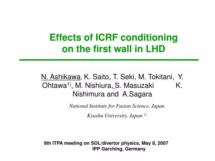
Effects of ICRF conditioning on the first wall in LHD. N. Ashikawa , K. Saito, T. Seki, M. Tokitani, Y. Ohtawa 1) , M. Nishiura, S. Masuzaki K. Nishimura and A.Sagara. National Institute for Fusion Science, Japan Kyushu University, Japan 1). Introduction.

E N D
Effects of ICRF conditioning on the first wall in LHD N. Ashikawa, K. Saito, T. Seki, M. Tokitani,Y. Ohtawa1), M. Nishiura,S. Masuzaki K. Nishimura and A.Sagara National Institute for Fusion Science, Japan Kyushu University, Japan 1)
Introduction ICRF conditioning (ICC) for recycling control / deducing impurities and T removal using He, D,O2 gasses • Investigation of effective area using material probes • Mode Conversion experiment with different frequency For Investigation of high energy tails, mode conversion experiment was done in 2006. As Heating efficiency of ICRF system, it was done in JET, C-mod and LHD. • M.-L. Mayoral et al., NF 46 (2006) S550. • Y. Lin, et al., POP 11 (2004) 2466. • K. Saito, et al., NF 41 (2001) 1021. It is important for antenna design in ITER. • In Helical device such as LHD, a confinement magnetic field during ICC is different in tokamaks. But a comparison between different operation scenarios using relative ratio can be possible. Resonance layer with Bt=2.75T, Rax=3.6m, f=38.47MHz (LHD)
Experimental setup in LHD • Bt=2.75T, Rax=3.6m • ICRF heating antennas at 3.5 and 7.5 port • Working gas was He (10-3-10-1Pa) • f=38.47MHz,85MHz • Duration time is 3 second (on), and interval time is 2 second (off). • Picrf=8-149kW (2004FY) -287 kW(2006FY) Hydrogen removal rate with He gasses by GDC is 10 times larger than ICC in LHD.
Plasma Material probes setup • From experiences (LHD, AUG, others), effective cleaning area by ICRF conditioning is considered smaller than by glow discharge • From damages area of material probes, effective cleaning area by ICRF conditioning was estimated. • Material holder was installed at the first wall level. • It have three kinds of facing. 1.Plasma Facing Area 2.Vertical direction 3.Gap (slit 1.5mm) Demonstration between divertor tiles
200nm Transmission Electron Microscopy (TEM) Analysis Bright field images,SS316L ×2 ICRF conditioning (about 4000s) Damages with He bubbles are observed only plasma facing area - Vertical : small - Gap : non Number of damages is depend on direction -it is suggested effective particles come to the wall straight -ICC is difficult for shadow area.
Mode Conversion Exp.(1) • High energy distributions were measured by Si fast neutron analyzer (FNA). • 38MHz,1.5T • 38MHz, 2.75T : He 2nd harmonics • 85MHz, 2.75T : electron accelerated mode • 85MHz(30%)+38MHz(70%) : mix • High energy ion particles were not observed at electron accelerated mode. • Tail distribution does not depend on an input power. High energy tails are observed on He 2nd harmonics mode (38MHz, 2.75T) • Natural Diamond Detector measured particle flux by ICC. • 1.6 – 3.2 x 10⁵at #70825 (38MHz, 2.85T, 287kW).
Mode Conversion Exp. (2) • 38MHz,1.5T : Low removal rate • Comparison of 38MHz and 85MHz with 2.75T : ?? (difficult) 38MHz, 1.5T • From comparison of modes with 1.5T, 38MHz w/o tails and 2.75T, 38MHz with tails, with high energy distribution mode have higher hydrogen removal rate. 85MHz 38MHz
Function of power density, Pin/(pV)1) 1)E. de la Cal PPCF(2005) Function of power density is used as a function of accelerating power to particles V; Volume of vacuum camber Pin; Input power of ICRF antenna. p; He partial pressure • Powers: -800kW(TEXTOR) • He Pressures: 0.55 Pa( HT-7) • Minimum estimation for ITER, about 100 kW/Pa m3 is shown using 0.01 Pa and 3MW (using pulse mode). Power density related to hydrogen removal rate
Summary • Using material probes, damaged area is observed in LHD. On the first wall level, only plasma facing area have damages with helium bubbles. A shadowed area have no damage. In future, we have a planning the same experiment in EAST. • From mode conversion experiment, different high energy distributions were measured during ICC. From comparison of modes with 1.5T, 38MHz w/o tails and 2.75T, 38MHz with tails, with high energy distribution mode have higher hydrogen removal rate. • Particle flux measured by NDD is 1.6 – 3.2 x 10⁵. • Comparison of hydrogen removal rate and power density of ICC shows a good relation. • Using new design parameters of -3 MW with 0.01 Pa for ICRF antenna, a power density of ICC in ITER is same level in current devices.