Download
1 / 17
170 likes | 361 Views
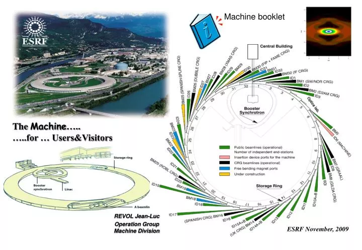
Machine booklet. The Machine ….. …..for … Users&Visitors. REVOL Jean-Luc Operation Group Machine Division. ESRF November, 2009. L’ESRF en chiffres. L’ESRF est une société civile de droit français, financée par 19 pays.

E N D
Machine booklet The Machine….. …..for … Users&Visitors REVOL Jean-Luc Operation Group Machine Division ESRF November, 2009
L’ESRF en chiffres L’ESRF est une société civile de droit français, financée par 19 pays. L’ESRF est en opération depuis quinze ansInauguration: 30 Septembre 1994 Budget annuel : 80 M Euros. Répartition du budget % France 27,5 Allemagne 25,5 Italie 15 Royaume-Uni 14 Espagne 4 Suisse 4 Benesync 6 (Belgique, Pays-Bas) Nordsync 4 (Danemark, Finlande, Norvège, Suède) Partenaires scientifiques : Portugal 1 Israël 1 Autriche 1 Pologne 1 Centralsync 1,05 (République tchèque, Hongrie, Slovakie) Environ 40 stations expérimentales anneau 844 mètres de circonférence Taux de disponibilité du faisceau 2008: 98.4% Temps moyen entre deux pannes 2008: 64 heures 600 Employés originaires de 30 pays En 2008: 2000 Propositions de recherche ~ 6300 Utilisateurs, 1500 Sessions expérimentales ~ 1500 Publications scientifiques avec référé
Green =horizontal beta function Red = vertical beta function b- functions ID 5 m 5 m 5 m Even cells Odd cells Lattice: DBA 32 cells 16 High beta sections, 16 Low beta sections 32 Straight sections (1 injection, 3 RF, 28 for IDs) • 28 Straight Sections for Insertion Device beamlines equipped with: 6 wigglers 60 in-air undulator segments 8 in-vacuum undulators • 15 beamlines using bending magnet radiation Beam size and divergence
64 Dipoles Generation of emittance by radiation Electron 2 emits De at the exit of the bending magnet. same energy when crossing the magnet stay on the reference trajectory Electron 1 emits DE at the entrance of the bending magnet. lower energy when crossing the magnet larger curvature A horizontal beam size and divergence(or emittance) and an energy spread is created. 320 Quadrupoles 224 Sextupoles The electron beam position is continuously measured at 224 positions around the ring with a resolution of 1mm with averaging. This deviation is minimized by a global correction by SVD method, which is computed every 30 sec. The correction is applied at 96 positions in each plane using steerer magnets.
ID Design lu N S N S N S qmax Gap Determines K S N S N S N S Max Deflection qmax = Kmax / g • Choose value of lu. • Set K by altering the gap. X Bending magnet: How do insertion devices work ? Electrons emit photons in a direction tangent to their trajectory. This is synchrotron radiation. Wiggler: Incoherent Superposition Succession of alternating polarity magnet poles. Each of these bends the electron beam through an angle, which is larger than the natural emission angle (1/g). K > 3 Flux is enhanced by twice the number of poles Undulator: Coherent interference K < 3 Succession of alternating polarity magnet poles (more periods), each of which bends the electron beam through an angle in the order of the natural emission (1/g) q<1/g K is the deflection parameter K = 0.0934 lu [mm] Bpeak [T] In case of undulator, K ~ 1 - 2 More collimation in angle and energy More flux Photons remain in phase with the electrons constructive interference along the ID Undulator Photon beam emittance of one electron.
Kmax Kmin The energy of the fundamental on axis is given by: If K increases the energy fundamental peak of the undulator is decreasing. For large K the electric field is made up of narrow peaks resulting in a large number of harmonics in the spectrum The total power radiated by the device: • Most advanced 3GLS (=ESRF) are diffraction limited in: • Both the V and H planes for UV beams • In V plane for shorter wavelengths Based on the present radiator principle of an undulator, the ultimate limit has been reached. • A factor 30 (to 300) could still be gained in the H plane for X-ray (hard X-ray) sources. The design of the undulator should be adapted to the need of the beamline.
ID magnetic structures Out Of Vacuum Undulator Magnet array Min Gap e- Adjustable Gap Vacuum Tube Magnet array Gap min=11 mm In Vacuum Undulator Vacuum Tube Magnet array e- Adjustable Gap Pure permanent magnet 4 magnet blocks /period (much better sinusoidal field is produced by using 4 blocks) Material: NdFeB, Sm2Co17 Hybrid Magnet material NdFeB, Sm2Co17 Pole material Fe-Co low carbon steel Magnet array Gap min=5 mm Advantage of the in vacuum device:much smaller minimum gap, and hence larger Kmax for a given lu. advantage at high photon energies or for low energy machine. (between 30keV and 100 KeV at ESRF) Inconvenience: Complicated mechanical assembly under vacuum. More space needed for one segment. 80 % of ESRF IDS 20 % of ESRF IDs Slightly higher field at low gaps/period but field correction more difficult to perform NdFeB: High field (Br = 1.15T), low radiation resistance and less heat resistance. Sm2Co17: Lower field Br = 1.03T, good radiation and heat resistance. In air: NdFeB for its high field. In vacuum Sm2Co17, due to its higher radiation resistance
Brilliance = photons /s / mm2 /mrad2 /0.1% bandwidth E [GeV] =0.3 B [T]r [m] B=0.8 T r = 25 m Power Consumption: SR (200 mA)= 5650 kWSR (0 mA) = 4300 kWInjector: 2 000 kW = 4.6 MeV The power radiated around the length of the ring bending magnets by a current of 200 mA = 920 kW 14.4 kW /Dipole 9.3 MW stored Power generated by one undulator (1.6 m) = 3kW 2kW/mm2 at 200 mA Installed ID power = 250 kW (100 kW used)
10 mm externe 8 mm interne In-air Length =1.64 m In-vacuumLength =2.4 m (2.4 m bride à bride, 2m assemblage magnétique) Standard Cryogenic Standard Revolver
Front End Open = X-ray beam available at the beam line Angular pattern of the radiation produced by a 6 GeV filament and mono-energetic electron beam electron beam passing through a 20 periods undulator (K=1.35, Period= 46 mm) and observed at a distance of 27 m from the source at a photon energy of 27 keV corresponding to the 7 th harmonic on axis. (The small and bright central cone is the 7th harmonic emission while the rings correspond to harmonics 8, 9 and 10). Same parameters and convolution with the electron emittances of ESRF namely 4 nm (0.04 nm) in the horizontal (vertical) plane. Power Density produced by a U35 Undulator of the ESRF computed in the Far Field.
Fast beam motion Damping material has been installed to reduce vibration effects Gain of 3 in the horizontal plane. Fast horizontal and vertical global feedback reduce the noise in a bandwidth from 0.1 to 150 Hz: 32BPMs and 24 correctors, 4.4 kHz correction rate Gain = 4 in horizontal Gain = 2 in vertical Slow beam motion The electron beam position is continuously measured at 224 positions around the ring with a resolution of 1mm with averaging. The electron beam trajectory deviates at some locations from a circle of 844 m in circumference (in reality a reference orbit). This deviation is minimized by a global correction by SVD method, which is computed every 30 sec. The correction is applied at 96 positions in each plane using steerer magnets. Stability Criteria: Emittance growth < 20% 10% on beam size and 10% on beam divergence Ultra slow motion The alignment of the storage ring magnets is controlled every shutdown and the machine is re-aligned if needed. Typical RMS beam motion in high b straight sections A combination of slow control, mechanical damping links and fast global feedback brings the vibration and the slow motion to an acceptable level. The amplitude of very slow motion is still dominant.
Long term overview of electron beam stability (7 weeks) 10 % Refill Refill Refill Refill Exceeds 10% of beam size over long term Influence of the filling pattern Problem of referential: the ground itself is not an absolute reference in that range. Within 10% of horizontal beam size for more than 6 weeks Visible influence of the filling pattern 10 % Vertical electron fast beam motion Horizontal electron fast beam motion H Feedback ON V Feedback ON 0.82 mm rms 30 mm 80 mm 2.42 mm rms Medium term electron beam stability (2 days, uniform fill) The stability is corrected by the permanent closed orbit correction. Vertical stability at the limit of the criteria.
q Nucleus of an atom of the residual gas with a charge Ze q Permanent injection A way to improve performances in case of a short lifetime. Stable heat load on ring and beamlines. Higher average brilliance But needs the permanent running of the injector and Gating of data at the beamline during injection(due to degradation of the beam stability). Beam current decay 200 mA 175 mA Beam Lifetime t 12 Hours Lifetime = 80 Hours Rate of loss of particles: Compared to low energy machine (<3GeV), high energy rings have a much longer beam lifetime. Morning refill Evening refill Distribution in phase space is Gaussian For ESRF: No interest in multibunch (Lifetime = 80 h, current variation = 12% with 2 refills/day) Could be of interest in time structure mode of operation, but not compatible with the present cleaning process Elastic coulomb scattering on gas Injection from an empty ring with Front Ends Closed Dominant process for vacuum related effects Injection with Front Ends Open if stored beam is larger than 5 mA limitation by the transverse acceptance Objectives: Reduction of the thermal load variation during injection on beamline components • In multibunch: Thermal variation induced by the refilling (from 160 to 200 mA twice per day) has almost disappeared No realignment after injection Low injection frequency, thanks to the naturally long lifetime (as opposed to frequent topping-up) to avoid injection perturbation. Some beamlines use beam during injection to perform long scans. Bremsstrahlung: Inelastic scattering on gas Emission of photons energy loss limitation by the longitudinal acceptance Safety issue for beamlines due to high energy photons produced Touschek effect In 16 Bunch, Hybrid and 4 bunch mode the situation is less favorable: Reduced lifetime imposes more frequent injection to reduce the current variation. Cleaning process in the SR disrupts beam use during injection (for a few minutes). Dominant process in time structure modes High intensity high particle density in the bunches. Increased probability of collision between particles.
Operation planning Year 2009 User mode: 5648 Hours Machine Dedicated Time: 1288 Hours Shutdown: 1824 Hours Statistics
Many thanks to Laurent Hardy , Kirstin Colvin Laurent Farvacque. Many thanks to those colleagues who provided the information and the material used in this presentation (D Martin, J Chavanne, E Plouviez, J Jacob, JC Biasci, P Duru,P Elleaume,K Scheidt…)