Download
1 / 14
140 likes | 235 Views
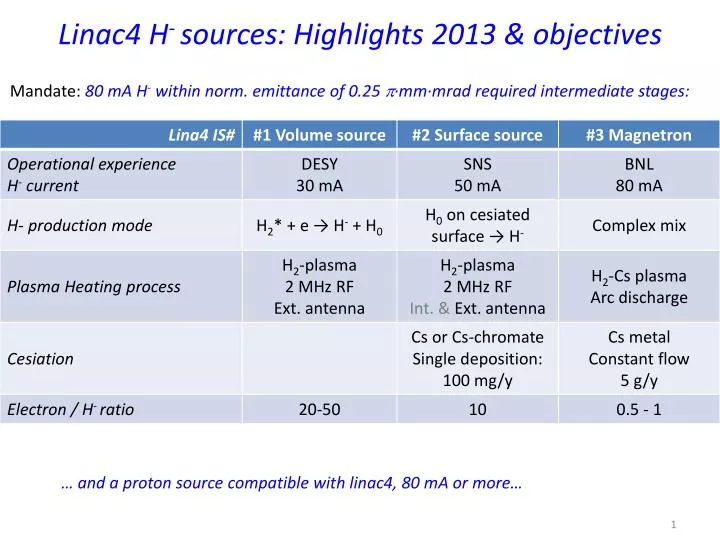
Linac4 H - sources: Highlights 2013 & objectives. Mandate: 80 mA H - within norm. emittance of 0.25 p ∙mm∙mrad required intermediate stages: . … and a proton source compatible with linac4, 80 mA or more…. Organization of the ISWP. Simulation - Measurements Bi-Weekly meeting

E N D
Linac4 H-sources: Highlights 2013 & objectives Mandate: 80 mA H- within norm. emittance of 0.25 p∙mm∙mrad required intermediate stages: … and a proton source compatible with linac4, 80 mA or more…
Organization of the ISWP • Simulation - Measurements • Bi-Weekly meeting • Beam-optics IBSimu • Pulsed H2 injection • High voltage, B-field (Opera) • Thermal equilibrium • RF-field (ANSYS HFSS) • Photo- Spectrometry Assembly / leak test IS, Production, Design & Vacuum -teams • Simulation Plasma • Bi-Weekly video meeting with KEIO university • Plasma heating • Light emission Collaborations BNL, IPP, SNS, RAL, J-PARC, Uni. Orsay, Uni. Jyvaskyla BE- ABP, CO, OP, RF EN- MME, MEF, HE, ICE, STI GS-SE, PH-DT TE- EPC, VSC, UHV-Cleaning
Thank you all Students & Fellows CERN J.P. Corso, J. Coupard, M. Wilhelmsson, F. Fayet, D. Steyeart, E. Chaudet, Y. Coutron, A. Dallocchio, P. Moyret, S. Mathot, Y. Body, R. Guida, P. Carriè, A. Wasem, J. Rochez, D. Aguglia, D. Nisbet, C. Machado, N. David, S. Joffe, P. Thonet, J. Hansen, N. Thaus, P. Chigggiato, A. Michet, S. Blanchard, H. Vertergard, M. Paoluzzi, M. Haase, A. Butterworth, A. Grudiev, R. Scrivens, M. O'Neil, P. Andersson, S. Bertolo, C. Mastrostefano, E. Mahner, J. Sanchez, I. Koszar, U. Raich, F. Roncarlo, F. Zocca, D. Gerard, A. Foreste, J. Gulley, C. Rossi, G. Bellodi, J.B. Lallement, M. Vretenar, A. Lombardi 8+19+50=77
IS front end ±3° Survey targets Y Z X o Plasma Generator Front End o H2 injection ±3° Alignment XYZ Support table ±15mm ±3mm Pumping Unit • Alignment table (Survey) • Beam based alignment options: Horiz. displacement & df, dw • Quick exchange in case of failure: • Pumping port • Front end
“Plug & play” Plasma Generator and beam formation region Pumping port 60 l/min TMP Secondary Vacuum IS01 Extraction region ±25kV Puller H2 Piezo Injection Ha light diffusing through The Al2O3 Chamber Ignition chamber • Exchangeable: • Plasma Generator • Flange + Extraction Optics • Ground electrode • Einzel lens • Insulators Plasma chamber ±10kV e-dump Einzel lens region Al2O3 insulator Pumping port 2×700 l/min TMP EPGM insulator
77 Identified contributors, 8 external institutions 19 TS, PhD & fellows (22 FTE) ABP-HSL’s Cesiated surface Linac4 H- source: How does it work ? Who made it possible ? H- IPP-Garching Cesiated Mo-surface SNS J-PARC Perm. Magnet cusp BE-RF solenoid antenna LPGP-Orsay Pulsed HVs -45 kV source 25 kV puller 10 kV dump Plasma view ports BE-BI Pulsed H2-inj. TE-EPC Ph-DT & TE-VAC Keio-Yokohama BNL-Upton NY ISIS-RAL Cs-oven EN-MME Most physics processes within this H- source are simulated, now entering engineering phase Jyvaskyla
IS02 Accumulated experience in conditioning & H-Production: • Notes on IS02: • Volume production 30 mA • Cesiated 60 mA • Cs-shortage: Strong anti-correlation between H- current and e-current • Improvement of e/H few hours after cesiation • Holds 100 kW RF • Plasma Generator cond.: 10 days • Volume production: 30 days • Cesiated surface: 80 days D-base operational
2013 highlights Sept. 2nd 2013: 1stH- beam in linac4 The very tight schedules of the 3MeV TS (mid. 2012) & L4-commissioning (sept.2013) is Matched • Flexible front end produced is suited for unprecedented IS-diversity : • Direct extraction of H- from the RF-H2 plasma volume (DesyVolume IS 20 mA) • Extraction of H-emitted form from a cesiated Mo-surface after impact of RF-H2 plasma produced H0 or p (SNS Surface IS 50 mA) • Extraction from an arc discharge induced Cs-H plasma (BNL’s Magnetron 100 mA) • Proton source (p, H2+, H3+) Dec. 13th 2013: First 50 mA pulse of the cesiatedsurface prototype Oct. 9th 2013: Nominal Linac4 beam tested @ BNL, 2 & 6.6 Hz Cs: 5 g/y Sept-2013
Objectives: 1) reliability 2) p-source 3) beyond 40 mA 2014-15 • Stabilization of the H- current • Increasing the availability to 99 % between technical stops • Optimizing mean time between maintenance • Demonstrate reactions to breakdowns via timing and operation procedures • Produce and test a proton source based on existing plasma generator • Produce and test the On-axis magnetron at 0.8 Hz at the IS-test stand • Tilted magnetron with Cs condensation
DB-correlations: Puller & H- beam currents vs. RF-power Puller: 4.6 mA/kW F. cup: -1.4 mA/kW The Rf-amplifier is facing the entrance door, its power is correlated to the room temperature
Proton, H2+, H3+source IS01 PG +45 kV • Boundary: compatible with existing front end. • Iteration between design and beam simulation on-going Puller 35 kV Einzel lens -35 kV
Modification of the Is-Front end: Large ceramic insulator Delivery: Ceramic insulator: March-April 2015 Deep flange Mtl. End Nov, Machining end January 2015 Today’s Front end
Simulation of BNL’s Magnetron with IBSimu • IBSimusettings: • H-beam current density is set to 1.6 A/cm2, resulting in a current of 100 mA. • Electron to H- ratio = ½ (50 mA) • A 3-D magnetic field map created in OPERA from the known magnet geometry and adjusting the field to a peak of 900 G. • Results: • The H- beam is transported through the puller at close to 100% efficiency. • 60 % of the co-extracted electrons (30mA), which trajectories are bent by the magnetic field, are dumped on the puller electrode tip. • 20 mA e-beam passes the puller electrode. -35 kV -45 kV e • J. Lettry, J. Alessi, D. Faircloth, A. Gerardin, T. Kalvas, H. Pereira, and S. Sgobba, Investigation of ISIS and BNL ion source electrodes after extended operation, Review of Scientific Instruments 83, 02A728 (2012). • H. Pereira, J. Lettry, J. Alessi and T. Kalvas, Estimation of Sputtering Damages on a Magnetron H- Ion Source Induced by Cs+ and H+ Ions, AIP Conf. Proc. 1515 (2013) pp.81-88. H-
Magnetron: BNL-test Post mortem, Status and outlook 2 stage extraction: Puller at 30 kV Molten W-tip https://edms.cern.ch/document/1352150/1 • Heated Anode body mandatory for 0.8Hz operation designed and ready for production • W-tip and broken isulator ceramics will be replaced.