Download
1 / 17
170 likes | 294 Views
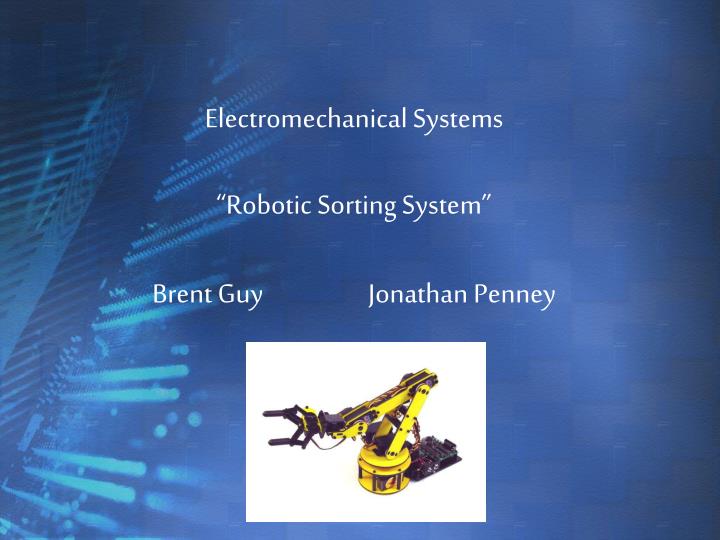
Electromechanical Systems “Robotic Sorting System” Brent Guy Jonathan Penney. Objectives. Design a robotic sorting system Construct a routine to locate test tubes Ignores locations if shelf is empty Transport them from storage shelf to desired location. Design Specifications.

E N D
Electromechanical Systems“Robotic Sorting System”Brent Guy Jonathan Penney
Objectives • Design a robotic sorting system • Construct a routine to locate test tubes • Ignores locations if shelf is empty • Transport them from storage shelf to desired location
Design Specifications Robotic arm has 2 major limitations: • Rotational limits • Height constraints Size of shelf compartments Weight of test sample
Design Evolution • Robotic arm with RGB sensor • 9 compartment shelf design • Puts samples on shelf • Robotic arm with IR Sensor • 3 compartment shelf design • Takes samples from shelf
Hardware PIC Microcontroller • 40-pin 16F877 embedded chip • Provides analog to digital conversion • Sends pulse waves to control servomotors
Hardware Servomotor • Pulse-proportional servos move the links • 180 degree range of motion • Positions are based on incoming pulses - 2500 units = 2.50 mS pulse (1 unit = 0.09 degrees)
Hardware SSC-32 Servo Controller • Integrated circuit board that controls servos • Servos plug into respective channels • Reads converted digital inputs from PIC
Hardware MAX232 Converter • Adjustsvoltage of signals socommunication can take placebetween PIC and SSC-32 • SSC-32: -10 V for logic one, +10 V for zero • PIC: +5 V for logic one, 0 V for zero
Hardware IR Proximity Sensor • Panasonic sensor with 2 LEDs • 4 – 26” range • Sensitivity adjusted by potentiometers • Information digitally sent to PIC
Software RIOS • Allows user to configure servos • Define positional limits of servos TTY • Provides direct serial communication • Allows for quick alterations * Final code produced in C
Programming a Servomotor Format: • # <Motor> P <Units> T<mSeconds> - E.g. #0 P1000 T3000 Moves motor 0 to position 1000 in 3 seconds
Pseudo Code • Set Initial Position • Scan A • If object present, grip and drop • If not, continue to B • Scan B • If object present, grip and drop • If not, continue to B • Scan C • If object present, grip and drop • If not, Set Initial Position
Difficulties • Missing link parts • Faulty servomotors • Short wires required splicing • Friction of base plate (removed 3 spokes) • Power source
Recommendations Future Use • Keep robot within suitable range (cannot move shelf without re-programming) • Infrared sensor has trouble detecting transparent tubes Improvements • RGB sensor • Add movement for transportation • Wheels • Track
Conclusion • Assembled Robot • Programmed • IR Sensor • Shelf Construction • Resulting in a functional robot that detects and transports test tubes for the biomedical industry