Download
1 / 32
320 likes | 475 Views
Charge collection in irradiated pixel sensors. Beam test measurements and simulation.

E N D
Charge collection in irradiated pixel sensors Beam test measurements and simulation V. Chiochiaa, C.Amslera, D.Bortolettoc, L.Cremaldid, S.Cucciarellie, A.Dorokhova,b*, C.Hörmanna,b, M.Koneckie, D.Kotlinskib, K.Prokofieva,b, C.Regenfusa, T.Roheb, D.Sandersd, S.Sonc, T.Speera, D.Kimf, M.Swartzf a Physik Institut der Universität Zürich-Irchel, 8057, Zürich, Switzerlandb Paul Scherrer Institut, 5232, Villingen PSI, Switzerlandc Purdue University, Task G, West Lafayette, IN 47907, USA d Department of Physics and Astronomy, Mississippi State University, MS 39762, USAe Institut für Physik der Universität Basel, Basel, Switzerlandf Johns Hopkins University, Baltimore, MD, USA * Now at: Institut de Recherches Subatomiques, F67037 Strasbourg, France
Outline • The CMS pixel detector • Radiation damage and pixel hit reconstruction • Analysis ingredients: beam test data and sensor simulation • Physical modelling of radiation damage: • Models with a constant space charge density • Double-trap models • Conclusions V. Chiochia – Charge collection in irradiated pixel sensors – TIME 05 - Zürich, October 3 -7, 2005
The CMS pixel detector ~1 m 0.3 m • 3-d tracking with about 66 million channels • Barrel layers at radii = 4.3cm, 7.2cm and 11.0cm • Pixel cell size = 100x150 µm2 • 704 barrel modules, 96 barrel half modules, 672 endcap modules • ~15k front-end chips and ~1m2 of silicon V. Chiochia – Charge collection in irradiated pixel sensors – TIME 05 - Zürich, October 3 -7, 2005
The LHC radiation environment • 4 cm layer F=3x10¹⁴ n/cm2/yr • Fluence decreases quadratically with the radius • Pixel detectors = 4-15 cm mostly pion irradiation • Strip detectors = 20-110 cm mostly neutron irradiation sppinelastic = 80 mb L = 1034 cm-2s-1 What is the sensors response after few years of operation? Fluence per year at full luminosity V. Chiochia – Charge collection in irradiated pixel sensors – TIME 05 - Zürich, October 3 -7, 2005
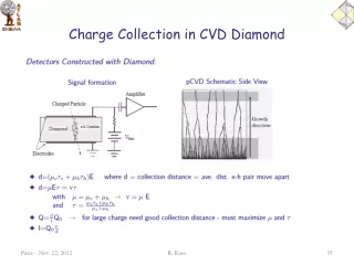
Radiation effects charge charge width charge width charge after irradiation after irradiation r-f plane r-zplane E E B field no B field Irradiation modifies the electric field profile: varying Lorentz deflection Irradiation causes charge carrier trapping V. Chiochia – Charge collection in irradiated pixel sensors – TIME 05 - Zürich, October 3 -7, 2005
Prototype sensors for beam tests 125 mm2 • n-in-n typewith moderated p-spray isolation, biasing grid and punch through structures (producer: CiS, Germany) • 285 μm thick <111> DOFZ wafer • 125x125 mm2 cell size, 22x32 pixel matrix • Samples irradiated with 21 GeV protons at the CERN PS facility • Fluences: Feq=(0.5, 2.0, 5.9)x1014neq/cm2 • Annealed for three days at +30º C • Bump bonded at room temperature to non irradiated front-end chips with non zero-suppressed readout, stored at -20ºC V. Chiochia – Charge collection in irradiated pixel sensors – TIME 05 - Zürich, October 3 -7, 2005
Beam test setup Silicon strip beam telescope: 50 μm readout pitch,~1 μm resolution CERN Prevessin site H2 area beam: 150 GeV p B field pixel sensor support Cooling circuit T =-30 ºC or -10ºC 3T Helmoltz magnet V. Chiochia – Charge collection in irradiated pixel sensors – TIME 05 - Zürich, October 3 -7, 2005
Charge collection measurement Feq = 2×10¹⁴ n/cm2 Feq = 6×10¹⁴ n/cm2 n+side p-side 2 years LHC low luminosity 2 years LHC high luminosity AGEING Charge collection was measured using cluster profiles in a row of pixels illuminated by a 15º beam and no magnetic field Feq = 5×10¹³ n/cm2 ½ year LHC low luminosity V. Chiochia – Charge collection in irradiated pixel sensors – TIME 05 - Zürich, October 3 -7, 2005
Detector simulation Charge transport ROOT Analysis Trapping ISE TCAD 9.0 Double traps models (DESSIS) 3-D Electric field mesh Trapping times from literature ROC+ADC response Electronic response + data formatting Charge deposit PIXELAV V. Chiochia – Charge collection in irradiated pixel sensors – TIME 05 - Zürich, October 3 -7, 2005
The classic picture • After irradiation the sensor bulk becomes more acceptor-like • The space charge density is constant and negative across the sensor thickness • The p-n junction moves to the pixel implants side • Sensors may be operated in “partial depletion” after type inversion Neff=ND-NA<0 Based on C-V measurements! - …is all this really true? V. Chiochia – Charge collection in irradiated pixel sensors – TIME 05 - Zürich, October 3 -7, 2005
Models with constant Neff F = 6x10¹⁴ n/cm2 Amodel based on a type-inverted device with constant space charge density across the bulk does not describe the measured charge collection profiles V. Chiochia – Charge collection in irradiated pixel sensors – TIME 05 - Zürich, October 3 -7, 2005
Two traps models acceptor EC-0.525 eV donor EV+0.48 eV EConduction Electron traps 1.12 eV Hole traps EValence EA/D= trap energy level fixed NA/D = trap densities extracted from fit se/h = trapping cross sections extracted from fit Model parameters (Shockley-Read-Hall statistics): V. Chiochia – Charge collection in irradiated pixel sensors – TIME 05 - Zürich, October 3 -7, 2005
The double peak electric field n+p junction np+ junction -HV PN junctions at both sides of the detector p-like n-like c) Space charge density a) Current density detector depth detector depth b) Carrier concentration d) Electric field V. Chiochia – Charge collection in irradiated pixel sensors – TIME 05 - Zürich, October 3 -7, 2005
Fit results Electric field and space charge density profiles • Data --- Simulation F1=6x10¹⁴ n/cm2 NA/ND=0.40 sh/se=0.25 V. Chiochia – Charge collection in irradiated pixel sensors – TIME 05 - Zürich, October 3 -7, 2005
Scaling to lower fluences • Near the ‘type-invesion’ point: the double peak structure is still visible in the data! • Profiles are not described by thermodynamically ionized acceptors alone • At these low bias voltages the drift times are comparable to the preamp shaping time (simulation may be not reliable) F3=0.5x10¹⁴ n/cm2 NA/ND=0.75 sAh/sAe=0.25 sDh/sDe=1.00 V. Chiochia – Charge collection in irradiated pixel sensors – TIME 05 - Zürich, October 3 -7, 2005
Scaling summary • Donors concentration increases faster than acceptors • NA/ND increases for decreasing fluences • Electric field peak at the p+ backplane increases with irradiation n-type ND space charge density p-type NA sensor depth (mm) V. Chiochia – Charge collection in irradiated pixel sensors – TIME 05 - Zürich, October 3 -7, 2005
Lorentz deflection LHC startup 2 years LHC low luminosity 2 years LHC high luminosity Switching on the magnetic field tan(L) linear in the carrier mobility (E): The Lorentz angle can vary a factor of 3 after heavy irradiation: This introduces strong non-linearity in charge sharing V. Chiochia – Charge collection in irradiated pixel sensors – TIME 05 - Zürich, October 3 -7, 2005
Conclusions and plans • After heavy irradiation trapping of the leakage current produces electric field profiles with two maxima at the detector implants. The space charge density across the sensor is not constant. • A physical model based on two defect levels can describe the charge collection profiles measured with irradiated pixel sensors in the whole range of irradiation fluences relevant to LHC operation • Our model is an effective theory: e.g. in reality there are several trap levels in the silicon band gap after irradiation. However, it is suited for applications related to silicon detector operation at LHC. • We are currently using the PIXELAV simulation to develop hitreconstruction algorithms optimized for irradiated pixel sensors. Results expected soon! V. Chiochia – Charge collection in irradiated pixel sensors – TIME 05 - Zürich, October 3 -7, 2005
References • PIXELAV simulation: • M.Swartz, “CMS Pixel simulations”, Nucl.Instr.Meth. A511, 88 (2003) • Double-trap model: • V.Chiochia, M.Swartz et al., “Simulation of Heavily Irradiated Silicon Pixel Sensors and Comparison with Test Beam Measurements”, IEEE Trans.Nucl.Sci. 52-4, p.1067 (2005), eprint:physics/0411143 • V. Eremin, E. Verbitskaya, and Z. Li, “The origin of double peak electric field distribution in heavily irradiated silicon detectors”, Nucl. Instr. Meth. A476, pp. 556-564 (2002) • Model fluence dependence: • V.Chiochia, M.Swartz et al., “A double junction model of irradiated pixel sensors for LHC”, submitted to Nucl. Instr. Meth., eprint:physics/0506228 (2005) V. Chiochia – Charge collection in irradiated pixel sensors – TIME 05 - Zürich, October 3 -7, 2005
Backup slides V. Chiochia – Charge collection in irradiated pixel sensors – TIME 05 - Zürich, October 3 -7, 2005
EVL models F1=6x10¹⁴ n/cm2 100% observed leakage current s=1.5x10⁻¹⁵ cm2 30% observed leakage current s=0.5x10⁻¹⁵ cm2 The EVLmodel based on double traps can produce large tails but description of the data is still unsatisfactory V. Chiochia – Charge collection in irradiated pixel sensors – TIME 05 - Zürich, October 3 -7, 2005
Advanced EVL models • The recipe: • Relax the assumption on the cross sections • Let the parameters (NA, ND, sA/De, sA/Dh) vary • Keep the traps energy levels (EA, ED) to the EVL values • Constraints to the model: • Charge collection profiles (at different Vbias and Feq) • Trapping rates • Generated leakage current be/h from literature Feq known within 10% V. Chiochia – Charge collection in irradiated pixel sensors – TIME 05 - Zürich, October 3 -7, 2005
E-field profiles Constant space charge density Double trap model V. Chiochia – Charge collection in irradiated pixel sensors – TIME 05 - Zürich, October 3 -7, 2005
Scaling to lower fluences (1) Preserve linear scaling of Ge/h and of the current with Feq F2=2x10¹⁴ n/cm2 NA/ND=0.68 sAh/sAe=0.25 sDh/sDe=1.00 ! Not shown: Linear scaling of trap densities does not describe the data! V. Chiochia – Charge collection in irradiated pixel sensors – TIME 05 - Zürich, October 3 -7, 2005
Temperature dependence F1=6x10¹⁴ n/cm2 • Charge collection profiles depend on temperature • T-dependent recombination in TCAD and T-dependent variables in PIXELAV (me/h, Ge/h, ve/h) • The model can predict the variation of charge collection due to the temperature change T=-25ºC T=-10ºC V. Chiochia – Charge collection in irradiated pixel sensors – TIME 05 - Zürich, October 3 -7, 2005
Lorentz deflection Lorentz angle Electric field V. Chiochia – Charge collection in irradiated pixel sensors – TIME 05 - Zürich, October 3 -7, 2005
Lorentz angle vs bias • ‘Effective’ Lorentz angle as function of the bias voltage • Strong dependence with the bias voltage (electric field) • Weak dependence on irradiation • This is a simplified picture!! Magnetic field = 4 T V. Chiochia – Charge collection in irradiated pixel sensors – TIME 05 - Zürich, October 3 -7, 2005
ISE TCAD simulation V. Chiochia – Charge collection in irradiated pixel sensors – TIME 05 - Zürich, October 3 -7, 2005
PIXELAV simulation V. Chiochia – Charge collection in irradiated pixel sensors – TIME 05 - Zürich, October 3 -7, 2005
SRH statistics V. Chiochia – Charge collection in irradiated pixel sensors – TIME 05 - Zürich, October 3 -7, 2005
SRH generation current V. Chiochia – Charge collection in irradiated pixel sensors – TIME 05 - Zürich, October 3 -7, 2005
Test beam setup pixel sensor Magnetic field = 3 T • Four modules of silicon strip detectors • Beam telescope resolution ~ 1 m • Sensors enclosed in a water cooled box (down to -30ºC) • No zero suppression, unirradiated readout chip • Setup placed in a 3T Helmoltz magnet or PIN diode trigger V. Chiochia – Charge collection in irradiated pixel sensors – TIME 05 - Zürich, October 3 -7, 2005