Download
1 / 20
200 likes | 311 Views
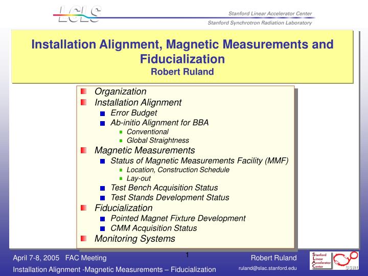
Installation Alignment, Magnetic Measurements and Fiducialization Robert Ruland. Organization Installation Alignment Error Budget Ab-initio Alignment for BBA Conventional Global Straightness Magnetic Measurements Status of Magnetic Measurements Facility (MMF)

E N D
Installation Alignment, Magnetic Measurements and FiducializationRobert Ruland • Organization • Installation Alignment • Error Budget • Ab-initio Alignment for BBA • Conventional • Global Straightness • Magnetic Measurements • Status of Magnetic Measurements Facility (MMF) • Location, Construction Schedule • Lay-out • Test Bench Acquisition Status • Test Stands Development Status • Fiducialization • Pointed Magnet Fixture Development • CMM Acquisition Status • Monitoring Systems
Undulator Alignment Tolerance • Undulator • The measured values for Keff shall be within ± 0.0005 (i.e., ± 0.015%) of the design values(LCLS Undulator Requirements PRD 1.4 – 001) • 1.5*10-4 correlates to 70 µm in Y, about 180 µm in X • Quadrupoles • 3 µm in X and Y over ~140 m • Ab-initio alignment for BBA ~150 µm, desired 80 µm
Alignment Approach • Global alignment of 70 µm very tough • Instead will use BBA quads as alignment references for undulator segments • Quadrupole and undulator segments are rigidly coupled by “cradle” mounting system, undulator segments follow quads • BBA will align quad – undulator segment units to 3 µm level over undulator system length • 70 µm tolerance is “reduced” from global (~140 m length) to relative (cradle) • Relative alignment can be done on CMM in MMF
Ab-initio Alignment • Conventional alignment methods, Total Station, Laser Tracker, Digital Leveling yields ~200 µm • Adding additional observations should yield position uncertainty of less than 100 µm • Absolute measuring hydrostatic level measurements (ultra-sound sensor) • Absolute measuring stretched wire measurements (optical wire detection)
Installation Alignment Workflow • Will use standard installation alignment approach. Requirement: All components use registration features to preserve pre-alignment • Install and measure alignment network • Install floor anchors and foot plates • Align foot plates to better than 0.5 mm • Install granite tables onto foot plates • Re-measure alignment network • Align undulator mechanical supports and cams of mover system • Install cradles • Install Monitoring System: HLS and WPM • Align Cradles • Straightness measurements: Alignment Stretched Wire System, Portable HLS • Align Cradles
LCLS Magnet Measurements Facility • Proposed Location: Bldg 81, about 0.8 km away from tunnel • Sufficient power forHVAC & test equipment • Ground motion and vibration measurements did not indicate potential problems • Manageable space constraints • Construction Schedule • T1 Aug 04 (Engineering) • T2 Dec 04 (Final Construction Drawings) • T3 May 05 (Construction Start) • Beneficial Occupancy February 2006
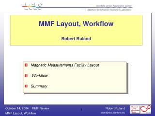
Layout • Floor plan divided into three functional areas • Magnetic Measurements (± 0.1º C) • Fiducialization and Assembly (± 1º C) • Storage (± 2.5º C) • Full set of specs: LCLS-TN-04-1 Z. Wolf, R. Ruland, "Requirements for the Construction of the LCLS Magnetic Measurements Laboratory“. • Test stand lay-out is driven by requirement to match the Earth Magnetic Field conditions in lab to Undulator Hall, i.e. azimuth and gap orientation need to be identical
Magnetic Measurements Undulator Test Bench #1 (8 m)final gap setting, final tuning Undulator Test Bench #2 (4 m) – existingprototyping procedures, software development,initial gap setting Hall Probe Calibration SystemTest magnet and NMR system Quad Integrated Field Strength BenchStretched Wire Quadrupole Fiducialization PlatformVibrating Wire Pointed-Magnet Fixture Calibration Bench Fiducialization & Assembly Fiducialization CMM 4.5 m Quadrupole Fiducialization PlatformVibrating Wire mounted on CMM BPM, Diagnostics Fiducialization MMF Set-up • Assembly • Cradle Assembly Bench • Vacuum Chamber Alignment BenchGranite table with Height Gauge • Undulator Segment / Cradle Storage • At least 2 Und. Segments in MM lab (0.1º C) • At least 2 Und. Segments in F&A lab (1º C) • 8 Cradles, quads, BPMs, Vacuum chamber and misc. supports in F&A lab (1º C) • About 20 undulator segments / cradles in storage area (2.5º C) Magnetic Measurements Facility Requirements, PRD 1.4 - 002
Undulator Test Bench Status • 8m Magnetic Measurements Test Bench (MMTB) Implementation Schedule • Evaluating RFP responses • Award expected for early May • delivery to coincide with MMF BO in Febr. 06 • Installation, commissioning, MMF ready for measurements 5/30/06 • Are using 5m bench obtained from APS for developing procedures and software (bench is being outfitted with equivalent hardware as 8m bench. • Will be using 5m bench for preliminary gap setting during production
Undulator Fiducialization & Cradle Alignment Will use Coordinate Measurement Machine (CMM) for mechanical fiducialization measurements and alignment of components on cradle • Specs: • 2µm +L/350 accuracy, • 4.5m x 1.2m x 1.0m volume • Min 1500kg load capacity • RFP being issued, due mid May • Award expected for early June • Delivery to coincide with BO of MMF
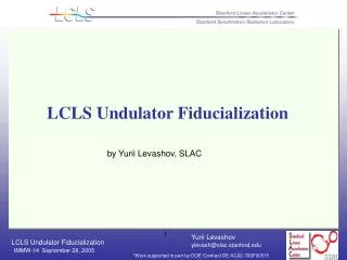
Undulator Fiducialization Status Proposed Method: Pointed Magnet Fixture • Step 1: measure offset between undulator axis and pointed-magnet reference fixture on MM Bench • Step 2: Measure pointed-magnet reference fixture wrt undulator fiducials on CMM • Test measurements show an accuracy of 10 µm in X and 5 µm in Y • See LCLS-TN-05-10 Y. Levashov and Z. Wolf, “Tests of coordinate transfer from magnetic to mechanical reference for LCLS undulator fiducialization”, in preparation
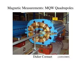
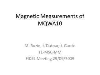
Quadrupole Fiducialization Status • Finding the axis • Will use Vibrating Wire prototype set-up. It promises better yaw and pitch resolution than pulsed wire. Implementation based on setup by Dr. Temnykh from Cornell • Completed prototype setup for permanent magnets. Routinely achieved repeatabilities even in environment with wide temperature swings of better than 5 µm • Test stand being re-designed for electro magnets • Transfer onto quadrupole fiducials • Use Wire Finders (developed for VISA) to locate wire and reference to its tooling balls • Use Coordinate Measurement Machine (CMM) to transfer information from WF to Quad fiducials. • Vibrating Wire system will be mounted onto optical table which can be set-up on undulator fiducialization CMM
Integrating Monitoring Systems into Cradle / Support System Since the cradle needs to be easily removable, we cannot attach the monitoring systems to it. Hence, both WPM and HLS need to be mounted to support table. However, the mounting has to be accomplish in a way which will force the sensors to follow the cradle motion
Hydrostatic Level System 3rd generation sensors with: Improved stability Changed interface from RS485 to TCP/IP over 10BaseT with POIP
END of Presentation