Download
1 / 66
660 likes | 662 Views
This article discusses the challenges of safely powering the superconducting magnet systems in the Large Hadron Collider (LHC). It covers topics such as individual tests, short circuit tests, hardware commissioning, main dipole current regulation, idle tones, and inner triplet powering. The article also includes information on LHC power converters, their installation and operation, and the need for electrical segmentation of the machine.

E N D
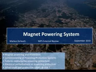
Commissioning of the LHC Super- conducting magnet systems The challenges of safely powering the super-conducting magnets Quentin King on behalf of Freddy Bordry With thanks to Valerie Montabonnet, Dave Nisbet, Hugues Thiesen, Yves Thurel, Greg Hudson, Andrea Cantone and Jeff Thomsen
Definition of LHC Powering • Individual Tests • Short Circuit Tests • Hardware Commissioning • Main Dipole Current Regulation • Idle Tones • Inner Triplet Powering • Transfer Function Analysis (demo)
Definition of LHC Powering • Individual Tests • Short Circuit Tests • Hardware Commissioning • Main Dipole Current Regulation • Idle Tones • Inner Triplet Powering • Transfer Function Analysis (demo)
= MONEY $$$ Definition of the Powering • For every circuit the accelerator physicists define: • The range of field strengths • Rates of change, accuracy, ripple, etc… • These are translated by the choice of magnets in powering requirements: • Current range • Ramp rate • Ripple • Accuracy • Resolution • Reproducibility
P o i n t 4 P o i n t 5 R a d i o f r e q u e n c y C M S a c c e l e r a t i o n s y s t e m SR5 RR53 SR4 UA47 RR57 UA43 SR6 UA63 UJ33 P o i n t 6 B e a m d u m p USC55 P o i n t 3 UJ56 UA67 SR3 Reference magnets in SM18. Orbit Corrector Power Converters distributed around arc tunnel. UA27 SR7 RR73 UA23 S P S SR1 P o i n t 7 UA83 P o i n t 2 Betatron Cleaning SM18 UA87 A L I C E RR77 RR17 RR13 T I 2 I n j e c t i o n P o i n t 8 T I 8 L H C - B UJ16 P o i n t 1 UJ14 I n j e c t i o n A T L A S
LHC Power Converters • Underground installation • Low volume, low weight • Only front access possible • no access during operation • High efficiency (>80%) • EMC • Water cooling (90% of the losses in water) • High reliability (MTBF 100’000 h) • Repairability and rapid exchange of different parts • High precision • DC current • low voltage ripple, • perturbation rejection,… Number of Converters: 1720 Total Current :1860 kA Steady State Input : 63 MW Peak Input : 86 MW
LHC : 1232 SC Main Dipole magnets Magnet inductance : L = 108 mH Ltotal=1232 * 0.108 = 133 H Ramp: LdI/dt = 1330V Discharge (quench; 120 A/s): 16kV Nominal current 11.8 kA Stored Energy = 9.3 GJ Ultimate current = 13kA Stored Energy = 11.3 GJ L/R 50 hours !!!! One circuit or several circuits ?
Why an Electrical Segmentation of the machine? • Natural segmentation into 8 units as no cryostat in straight sections. • Warm cable connections costly in copper, power losses (~30MW instead of 10MW) and power converters • Only 1/8 of the machine needs to be discharged if one magnet quenches • No risk of total machine avalanche quench, (false quench detection and provocation • Eight sub-units give easier installation, testing, commissioning and fault finding for many systems • Allows sector-to-sector correction of magnet errors due to different cable, magnet manufacturers, etc.. • Need to track from sector to sector
Tracking between the 8 main dipole converters ppm Accuracy DB/Bnom = DI/Inom = ppm DB = 9 10-6 = 1.8 10-4 T DB/Bo = 15 10-6 Orbit excursion : dX = Dx . DB/Bo = ~ .035 mm dX = .7 mm=> = 20 ppm Could be corrected with a pilot run and new cycle => reproducibility 10 ppm reproducibility Orbit excursion : dX = Dx . DB/Bo = ~ 0.35 mm !!! “It would be better with 5 ppm” Oliver Brüning
Control Precision Power ConverterTolerances for LHC
UA23 (Ex-LEP Klystron gallery) Now used to house the majority of machine equipment including power converters Very Low Radiation Dose
New Enlargement (RR) for Machine Power Converters around ATLAS and CMS 600A 6kA Constraints : Volume, back-to-back, losses, weight and radiation!
Orbit Corrector PCs 4*[60A,8V] 752 converters Main Arc Tunnel High reliability : MTBF : 80 ’000 h 1 converter breakdown every 4 days One campaign every 2 or 3 months Radiation Dose 1-2 Gy/year under dipoles
The Challenges : • Performance : • High current with high precision (accuracy, reproducibility, • stability, resolution) and large dynamics • current range (for 1-quadrant converter: from 1% to 100%) • a lot of 4-quadrant converters (energy from magnets) • - tracking : Need to track from sector to sector • - voltage ripple and perturbation rejection Installation and Operation: - volume (a lot of converter are back-to-back) - weight (difficult access) => modular approach - radiation for [±60A, ±8V] converters (and others too!) - extraction of losses : high efficiency, water cooling - EMC : very close to the others equipment ; system approach
Definition of LHC Powering • Individual Tests • Short Circuit Tests • Hardware Commissioning • Main Dipole Current Regulation • Idle Tones • Inner Triplet Powering • Transfer Function Analysis (demo)
A Selection of LHC Converters A Selection of LHC Converters Atlas Torroid Point 8: Main Dipole (RB) Point 4: 120A Point 4: 600A
Power Part (Voltage Source) AC Mains Supply Magnets What is a power converter? Cooling System Power Interlock Controller Vref Function Generator Current loop Current Transducer DCCT WorldFIP fieldbus
Individual Tests at the suppliers Individual Tests at CERN PC Integration and test at CERN Power Part Power Part Power Part FGC Dcct FGC FGC LHC PC Dcct Dcct PC Tests Before Installation
FGC Individual Tests Individual cards were tested after production by the manufacturer using automatic testers provided by CERN Completed FGCs run for at least a month in special “Reception” crates in Bat. 866
Class1 DCCTs (13kA) - Highest performance - state of the art - Separate Head and electronics chassis 19” rack mounting - Fitted with Calibration Windings - Temperature-controlled environment in the Accelerator. - Full testing and calibration at CERN on the 20kA Test Bed.
4kA to 8kA DCCTs Other DCCTs 600A DCCTs 120A DCCTs
Definition of LHC Powering • Individual Tests • Short Circuit Tests • Hardware Commissioning • Main Dipole Current Regulation • Idle Tones • Inner Triplet Powering • Transfer Function Analysis (demo)
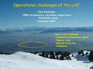
Short-circuit tests are not only power converter tests: energy extraction tests, DC cables tests, AC network conditions, cooling and ventilation, interlocks, control,… Short-circuit tests (SCT)
Short-circuit tests From October 2005 to September 2007 All tests were successfully concluded by a 24h endurance test (16h at ultimate and 8h nominal)
kW 1400.0 Total 1200.0 1000.0 Other PC 800.0 600.0 400.0 Dipole 200.0 0.0 Power measured by TS-EL in SE8 Power consumption during 24 Hour Short-circuit tests
Air Temperature during 24 Hour Short-circuit tests 32 31 30 29 28 27 27.5 ºC 20 ºC 27 ºC 18.5 ºC ? ºC ? ºC 33 ºC 33 ºC 30? ºC 20? ºC 30 ºC 20 ºC 3500 m3/h 5000 m3/h 3500 m3/h RB Temp (18H00) 28 sat 32 sat (19H00) 27 sat (13H00) 27, 28 & 32 29 J. Thomsen
UJ33 24 Hour Run – Systematic Infra Red (IR) survey Y. Thurel 80.3°C 90°C
Systematic Infra Red (IR) survey An Infra Red analysis to see what a hand cannot feel at less than 20cm !!! 275°C due to a loose connection Y. Thurel
Systematic Infra Red (IR) survey 4 racks with 8 * [±600A;±10V] in UA 67 An Infra Red analysis shows that everything is OK Y. Thurel
Definition of LHC Powering • Individual Tests • Short Circuit Tests • Hardware Commissioning • Main Dipole Current Regulation • Idle Tones • Inner Triplet Powering • Transfer Function Analysis (demo)
Tracking between the main circuits of sector 78 • Test Method: • Current Channel A swapped • Regulation with Channel B RB, RQD, RQF synchronized ramp Dave Nisbet
Tracking between the main circuits of sector 78 RB/QF/QD Tracking – 350A to 2kA Dave Nisbet
2ppm Free-wheeling : L/r 23’000 s Tracking between the main circuits of sector 78 Dave Nisbet
Powering of Q4 MQM Matching Sections - Current loop robustness: L/2r to L/r - Always: static and dynamic I1/2 < I2 < 2xI1 and I2/2 < I1 < 2xI2 Dave Nisbet
Squeeze tests (PSQ) : Q4 and Q5 • RQ4.L8B2 is close to limit • New optic function much improved (15min squeeze) • All systems performed as calculated • With LHC Software Application • LSA: generation of table (I,t) • MQM control touchy during ramp down with • 1-Quadrant converter • Good Performance even if the limits are close RQ5.L8B2 I_MEAS RQ5.L8B1 V_MEAS RQ5.L8B1 I_MEAS RQ5.L8B2 V_MEAS RQ4.L8B2 I_MEAS RQ4.L8B2 V_MEAS RQ4.L8B1 I_MEAS RQ4.L8B1 V_MEAS Close to Limits 0V Dave Nisbet
Converter Operation during a sub-converter failure V. Montabonnet
3.25 kA , 18 V 13 kA, 18V 1 ms 3.25 kA , 18 V 1625 A 1300 A Vout Restart of sub-converter 2 3.25 kA , 18 V 3.25 kA , 18 V 6500 A 3.25 kA , 18 V At injection current : 860 A I_MEAS = About 1-2ppm pk-pk Converter Operation during a sub-converter failure [13kA,18V] converter : (4+1) x [3.25kA,18V] subconverters Tests during 7-8 hardware commissioning V. Montabonnet
Definition of LHC Powering • Individual Tests • Short Circuit Tests • Hardware Commissioning • Main Dipole Current Regulation • Idle Tones • Inner Triplet Powering • Transfer Function Analysis (demo)
1.9K 4.5K Main dipole circuit powering by RB converter
First powering of a Sector 78 main dipoles 45 V The Inductance changes below 120A! 350 A 3 A/s 15.5 H 12.6 H
First powering of a Sector 78 main dipoles The first ramp from 300A to 350A
7 ppm (100 mA) First powering of a Sector 78 main dipoles No tracking error
2 ppm (20mA) First powering of a Sector 78 main dipoles No overshoot
Main dipole Power Converter: Start Up • Start up must avoid rapid voltage changes that can trigger the QPS • If current is less than 1% of I_MIN then a blocking voltage must be applied during the pre-mag phase – this winds up the voltage loop integrators • This could result in an aggressive start up that could trip the RB QPS so ~6s open loop voltage ramp is now included to make the start up smoother: The FGC regulates dI/dt by controlling dV/dt with a proportional controller New open loop voltage ramp included until I > 1% of I_MIN RB successfully started at 10 A/s Blocking voltage during Pre-Mag
Main dipole Power Converter: Power Off • RB decay from 350A takes more than 1 hour with the discharge switch closed • New Switch Off algorithm ramps down the current to 1% of I_MIN (< 4 A) before switching off in about 1 minute • The algorithm is also be used for SLOW ABORT End of a Switch Off ramp on RB dI/dt of ramp down is regulated by controlling dV/dt with a proportional controller Converter is switched off with V_REF = 2% of V_NEG Voltage is reduced in proportion to the current to smoothly end the ramp to 1% of I_MIN
“Current capture” RB Failure → Unexpected succesful test Earth Fault Detected → RB Trip @ 9kA 9kA • RB OFF => ON @ 5kA • Current captured • I Loop closed → No Need to open switch saves time • → QPS does not trip I.meas 5kA I.ref PO In Action PO specialists mobilized → Problem diagnosed as a weak component Not a TRUE earth fault → Repair made on LIVE circuit (5kA circulating) 1h30 Load Time constant 13 740 sec (4 hours). Time 9kA → 0A is more than 7hours
Definition of LHC Powering • Individual Tests • Short Circuit Tests • Hardware Commissioning • Main Dipole Current Regulation • 22-bit ADC Idle Tones • Inner Triplet Powering • Transfer Function Analysis (demo)
Andrea Cantone Spikes on the RB/QF/QD current of 20 ppm peak-peak were seen around 820A and 900A All ADCs tested had the same behavior although the DC levels varied slightly Measurements in the lab revealed idle tones at the same DC input levels as seen in RB Problem was traced to a non-optimal digital filter function. A new function was developed and distributed over the network – no hardware change was required 900AUp to 20ppm 820A Up to 20ppm RB, QF & QD use high precision ADCS