Download
1 / 13
140 likes | 145 Views
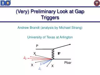
Preliminary considerations on the CLIC DR wiggler gap definition. K. Zolotarev BINP, Novosibirsk 25 April 2008. Problem Description. To minimize emittance by damping wigglers, high peak field and short period length of the wiggler are required.

E N D
Preliminary considerations on the CLIC DR wiggler gap definition K. Zolotarev BINP, Novosibirsk 25 April 2008
Problem Description To minimize emittance by damping wigglers, high peak field and short period length of the wiggler are required. And as the peak field, period length and the wiggler gap relate to each other as the wiggler gap definition is an important task. Below we consider the wiggler gap definition from a viewpoint of the SR power propagation through the wiggler chamber only. Other relevant issues are resistive wall heating, impedances, etc.
Model A 4-wiggler scheme • In FODO cell the vertical collimators are located in the horizontally focusing quadrupoles (beta-y is low) • At the LHe-temperature wiggler chamber the linear power density less than 1 W/m is acceptable (Remo Macceferri) • The wiggler length is 2 m and the drift length between the wigglers is 1 m (quad, BPM, steering magnets, bellow, etc.) • W2 is illuminated by W1 (W4 by W3) and as we can not collimate this radiation vertically, it defines the min wiggler gap • W4 is illuminated by W1+W2+W3 and this fact gives the height of the collimator • On-axis radiation; no COD is considered!
Parameters CLIC-DR parameters Wiggler parameter (from Remo)
Absorbers for Petra-III 20 kW per absorber
Min wiggler gap W2 is illuminated by W1 and to have 1 W/m of the linear radiation power density at the W2 chamber wall the gap around 10 mm is needed. SR power density at the W2 upper (lower) wall due to the radiation from W1. Ptot =2.2 W at 2 m-long wall Beam direction Ptot vs wiggler gap Ptot 2 W at 10 mm gap
Ptot at W4 vs collimator slit height W. Gap Slit height 10 mm 1.5 mm 12 mm 2.5 mm 16 mm 6.0 mm Zoomed
SR density plot at W4 g =10 mm Slit = 1.5 mm g =12 mm Slit = 2.5 mm g =16 mm Slit = 6 mm g =20 mm Slit = 10 mm
Absorbers solution for gap 16 mm Abs.35 Abs.36
Conclusions • Wiggler gap is a main parameter defining the field amplitude and period length. • Reliable scheme for SR power evacuation from wiggler chamber is important task. • Optical solution of the wiggler straight section should corresponds to the collimator apertures • COD should be included in the final calculations