Download
1 / 17
170 likes | 292 Views
Universidade Estadual de Londrina. Estruturas. Resistência dos Materiais. TENSÕES. 01. BARRA SOB CARGA AXIAL. FORÇA POR UNIDADE DE ÁREA. COMPRESSÃO. ESFORÇO INTERNO. P. N=P. P. A. S’. S’. TENSÃO. P A. P A. P. P. P. σ =. EQUILÍBRIO. EQUILÍBRIO. (sigma).

E N D
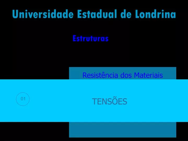
Universidade Estadual de Londrina Estruturas Resistência dos Materiais TENSÕES 01
BARRA SOB CARGA AXIAL FORÇA POR UNIDADE DE ÁREA COMPRESSÃO ESFORÇO INTERNO P N=P P A S’ S’ TENSÃO P A P A P P P σ = EQUILÍBRIO EQUILÍBRIO (sigma)
CONCEITO DE TENSÃO P1 P2 P3 ΣFr PARTE EM EQUILÍBRIO CORPO EM EQUILÍBRIO R2 R1 ΣFr FORÇAS RESISTENTES DA SEÇÃO
TENSÃO EM UM PONTO TENSÃO MÉDIA P1 P1 P2 P2 ΔF ΔF t ΔF ΔF T = ΔA P ΔA 0 ΔA R1 R1 ΔA 0 t = lim ΔA ΔA
Tensão normal na direção x TIPOS DE TENSÃO Y P1 P2 txy ΔFx ΔFz ΔFy Tensão tangencial na direção y sx t txz X ΔA 0 ΔA 0 ΔA 0 P txz = lim txy = lim Tensão tangencial na direção z R1 ΔA ΔA Z sx = lim ΔA Tensões atuantes no plano zy, cuja normal é x
ESTADO GERAL DE TENSÃO Tensões atuantes no plano xy (normal z) sztensão normal ao plano x-y na direção z tzytensão tangencial ao plano x-y na direção y tzxtensão tangencial ao plano x-y na direção x
TENSÃO NORMAL MÉDIA DISTRIBUIÇÃO MÉDIA DE TENSÃO HIPÓTESES • A barra deve • permanecer reta • e a seção plana • A carga deve • ser centroidal e o • material homogêneo • e isotrópico
TENSÃO NORMAL UNIFORME • Na seção de área A constante f f dF = σ dA • P = σ A • P • A • σ = • A = área da seção transversal σ = tensão normal média em qualquer ponto de A • P = resultante da força normal aplicada no centróide de A
EQUILÍBRIO • Σ FZ = 0 • σ(ΔA) – σ’(ΔA) = 0 • Estado uniaxial de tensões • σ = σ’
P - P 3P P 2P 3P P TENSÃO NORMAL MÉDIA MÁXIMA • 2A • A • P • A Diagrama de Esforços Normais • σ = Esforço 3P P Área 2A A Valores de σ = P/A P/A (1)P/A (1,5)P/A • TENSÃO MÁXIMA
TENSÃO DE CISALHAMENTO MÉDIA Tangente à superfície resistente F Tensões tangenciais ou de cisalhamento V V F Força aplicada seção resistente A C A P B F Elemento estrutural F med= tensão de cisalhamento média na seção tmed V A med = V = resultante interna da força de cisalhamento A = área da seção transversal resistente. (tau)
CISALHAMENTO SIMPLES METAL MADEIRA SEÇÃO SIMPLESMENTE CISALHADA JUNTA SOBREPOSTA FINOS APROXIMAÇÕES Despreza-se o momento fletor criado pela força F • ELEMENTOS DA JUNTA • PORCA DO PARAFUSO DE LIGAÇÃO Despreza-se o atrito entre os elementos V A med = NÃO MUITO APERTADA FORÇA ATUANTE V=F
CISALHAMENTO DUPLO METAL MADEIRA SEÇÃO DUPLAMENTE CISALHADA JUNTAS DE DUPLA SOBREPOSIÇÃO FINOS APROXIMAÇÕES Despreza-se o momento fletor criado pela força F • ELEMENTOS DA JUNTA • PORCA DO PARAFUSO DE LIGAÇÃO Despreza-se o atrito entre os elementos V A med = NÃO MUITO APERTADA FORÇA ATUANTE V=F/2
EQUILÍBRIO ESTADO DE TENSÕES tensão x área = força CONSIDERANDO : zy = ’zy zy(ΔxΔy) - ’zy(ΔxΔy) = 0 Σ Fy = 0 Momento=(tensãoxárea= força)xbraço Σ Fz = 0 yz = ’yz de maneira similar: zy= yz -zy(ΔxΔy)Δz + yz(ΔxΔz)Δy = 0 Σ Mx = 0 zy = ’zy = yz= ’yz = CISALHAMENTO PURO ENTÃO:
TENSÃO ADMISSÍVEL SEM RUPTURA MÁXIMA TENSÃO NO MATERIAL SEM DEFORMAÇÕES EXAGERADAS TENSÃO QUE O MATERIAL PODE SUPORTAR TENSÃO ADMISSÍVEL < σadm adm σ JUSTIFICATIVAS MÉTODO ULTRAPASSADO • Carga de projeto diferente da carga aplicada • Carga acidentais não consideradas no projeto PARÂMETRO DE DIMENSIONAMENTO E VERIFICAÇÃO • Corrosão e desgaste dos materiais • Variação das propriedades dos materiais
A= PROJETO DE ACOPLAMENTO SIMPLES A= BARRA TRACIONADA P σadm
PROJETO DE ACOPLAMENTO SIMPLES A= P adm LIGAÇÕES SIMPLES