Download
1 / 33
710 likes | 1.9k Views
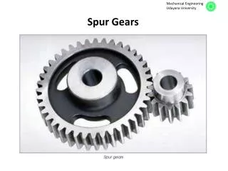
UNIT-II SPUR GEARS. Prepared by R.Sendil kumar. Gears - Introduction. Gears are toothed wheels used for transmitting motion and Power from one shaft to another, when they are not to far apart. Compare with belt, chain and friction drives, gear drives are more compact .

E N D
UNIT-IISPUR GEARS Prepared by R.Sendil kumar
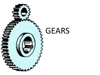
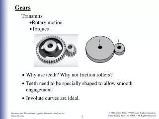
Gears - Introduction • Gears are toothed wheels used for transmitting motion and Power from one shaft to another, when they are not to far apart. • Compare with belt, chain and friction drives, gear drives are more compact. • It can operate at high speeds and can be used where precise timing is required. • It is used when large power is to be transmitted.
Definiton A circular body of cylindrical shape or that of the shape of frustum of a cone and of uniform small width, having teeth of uniform formation, provided on its outer circumferential surface, is called a gear or toothed gear or toothed wheel.
Classification of gears Classification based on the relative position of their shaft axes: • Parallel shafts Ex.: Spur gears, helical gears, rack and pinion, herringbone gears and internal gears. • Intersecting shafts Ex: Bevel gears and spiral gears. Classification based on the relative motion of the shafts: • Row gears The motion of the shafts relative to each other is fixed. • Planetary and differential gears
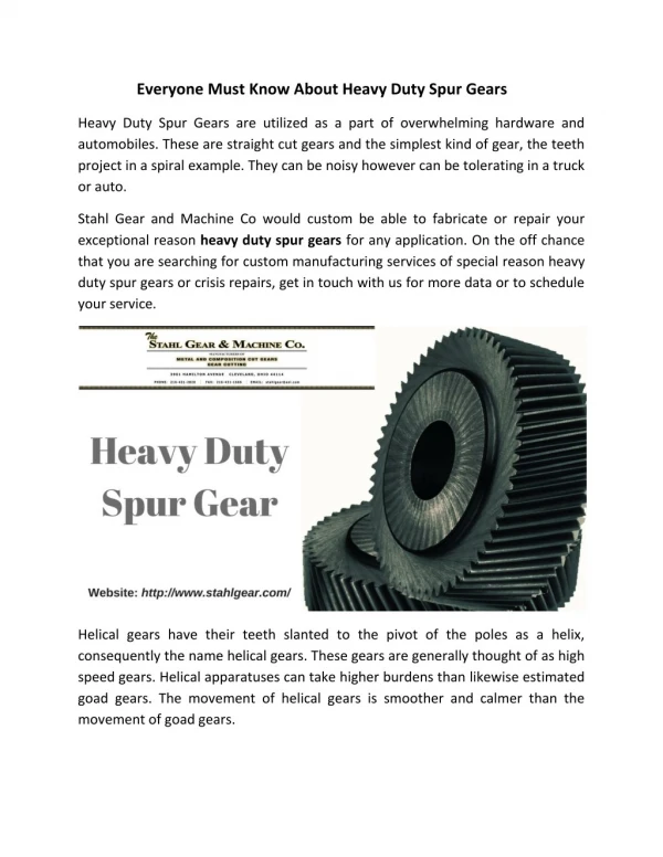
Contd… Classification based on peripheral speed (ν): • Low velocity gears – ν < 3 m/s • Medium velocity gears – ν = 3 to 15 m/s • High velocity gears – ν > 15 m/s Classification based on the position of teeth on the wheel: • Straight gears • Helical gears • Herringbone gears • Curved teeth gears Classification based on the type of gearing: • External gearing • Internal gearing • Rack and pinion
Terminology Used in Gears • Pinion • Pitch circle • Pitch circle diameter • Pitch point • Pitch surface • Pitch Circular pitch (pc): Pc = πD/z D = Dia. Of pitch circle z = No. of teeth on the wheel Diametral pitch (pd): pd = z/D = π/pc Module pitch (m): m =D/z
Contd… • Addendum circle (or Tip circle) • Addendum • Dedendum circle (or Root circle) • Dedendum • Clearance • Total depth = Addendum + Dedendum • Working depth • Tooth thickness • Tooth space • Backlash = Tooth space – Tooth thickness • Face width
Contd… • Top land • Bottom land • Face • Flank • Fillet • Pressure angle (or angle of obliquity): • It is the angle b/w the common normal to two gear teeth at the point of contact and the common tangent at the pitch point. The standard pressure angles are 14 1/2º and 20º
Contd… • Path of contact: • It is the path traced by the point of contact of two teeth from the beginning to the end of engagement. • Length of path of contact (or Contact length): • It is the length of the common normal cutoff by the addendum circles of the wheel and pinion. • Arc of contact: • It is the path traced by a point on the pitch circle from the beginning to the end of engagement of a given pair of teeth. The arc of contact consists of two parts. Arc of approach Arc of recess • Velocity ratio i = NA/NB = zB/zA • Contact ratio: Ratio b/w arc of contact to circular pitch
Advantages • There is no slip, so exact velocity ratio is obtained. • It is capable of transmitting large power than that of the belt and chain drives. • It is more efficient (upto 99%) • It requires less space as compared to belt and rope drives. • It can transmit motion at very low velocity, which is not possible with the belt drives.
Limitations • The manufacture of gears require special tools and equipments. • The manufacturing and maintenance costs are comparatively high. • The error in cutting teeth may cause vibrations and noise during operation.
Law of Gearing The law of gearing states that for obtaining a constant velocity ratio, at any instant of teeth the common normal at each point of contact should always pass through a pitch point (fixed point), situated on the line joining the centres of rotation of the pair of mating gears.
Gear Materials • The gear materials are broadly grouped into two groups, there are metallic and non-metallic materials. Metallic materials Steel: • The most widely used material in gear manufacture is steel. Almost all types of steels have been used for this purpose. • It having property of toughness and tooth hardness, steel gears are heat treated. • BHN < 350 – Light and medium duty drives • BHN > 350 – heavy duty drives
Contd… • For medium duty applications – Plain carbon steels 50C8,45C8,50C4 & 55C8 are used. • For heavy duty applications – alloy steels 40Cr1, 30Ni4Cr and 40 Ni3Cr1 and 40Ni3Cr65Mo55 are used. Cast Iron: • It is used extensively as a gear material because of its low cost, good machinability and moderate mechanical properties. • Large size gears are made of grey cast iron of Grades FG 200, FG 260 or FG 350. • Disadv: It has low tensile strength.
Contd… Bronze: • It is mainly used in worm gear drives because of their ability to withstand heavy sliding loads. • Bronze gears are also used where corrosion and wear a problem. Disadv: They are costlier Types: aluminium bronze, manganese bronze, silicon bronze, or phosphorus bronze. Non-metallic materials: • The non-metallic materials like wood, rawhide, compressed paper and synthetic resins like nylon are used for gears. Adv: (i) Noiseless operation, (ii) Cheaper in cost (iii) Damping of shock and vibration. Disadv: (i) Low load carrying capacity (ii) Low heat conductivity.
Selection of Gear Material • Type of service • Method of manufacture • Wear and shock resistance • Space and weight limitations • Safety and other considerations • Peripheral speed • Degree of accuracy required • Cost of the material • High loads, impact loads & longer life requirements
Gear Manufacturing Gear milling: • Almost any tooth can be milled. However only spur, helical and straight bevel gears are usually milled. • Surface finish can be held to about 3.2 μm. Gear generating: • Teeth are formed in a series of passes by a generating tool. • Hobs or shapers are normally used. • Surface finishes as fine as about 1.6 can be obtained. Shaping: • Teeth may be generated with either a pinion cutter or a rack cutter. • They can produce external and internal spur, helical, herringbone. Gear molding: • Mass production of gears can be achieved by molding.
Contd… Injection molding: • Injection molding produces light weight gears of thermoplastic material. Die casting: • It is a similar process using molten metal. Zinc, brass, aluminium & magnesium gears are made by this process. Sintering: • Sintering is used in small, heavy-duty gears for instruments and pumps. Iron and brass are mostly used for this process Investment casting: • Investment casting and shell molding produce medium-duty iron and steel gears for rough applications.
DESIGN PROCEDURE 1. Calculation of gear ratio (i): i = N1/N2 = z2/z1 If gear ratio is not specified, it may be assumed to be unity. In case of multistage speed reducers, the speed ratio may be selected from R20 series. 2. Selection of materials: From PSGDB – 1.40 or 1.9, knowing the gear ratio i, choose the suitable combination of materials for pinion and wheel. 3. If not given, assume gear life (say 20,000 hrs) 4. Calculation of initial design torque (Mt): (Mt) = Mt ×K×KdPSGDB – 8.15, T-13 Mt = Transmitted torque =
Contd… K = Load concentration factor, from PSGDB – 8.15, T-13 Kd = Dynamic load factor, from PSGDB – 8.16,T-15 Since datas are inadequate to select the values of K and Kd, initially assume K×Kd = 1.3 5. Calculation of Eeq, (σb) and (σc): • From PSGDB – 8.14, T-9, calculate the equivalent Young’s modulus (Eeq) • calculate the design bending stress (σb), from (PSGDB 8.18, below T-18) To find (σc): Calculate the desing contact stress (σc) (8.16, below, T-15) (σc) = CB×HB×Kcl (or) (σc) = CR×HRC×Kcl Where CB (or) CR= Coefficient depending on the surface hardness, from PSGDB – 8.16, T-16. HB or HRC = Brinell or Rockwell hardness number Kcl= Life factor for surface strength, from PSGDB – 8.17, T-17
Contd… 6. Calculation of centre distance (a): from PSGDB- 8.13, Table 8 Calculate the centre distance between gears based on surface compressive strength using the relation a ≥ ( i+1) ψ = = Width to centre distance ratio 7. Selection of number of teeth on pinion (z1) and gear (z2): • Number of teeth on pinion, z1: Assume z1≥ 17, say 18. • Number of teeth on gear, z2: z2 = i×z1
Contd… 8. Calculation of module (m): m = (PSGDB 8.22, T-26) Using the calculated module value, choose the nearest higher standard module from PSGDB – 8.2, T-1. 9. Revision of centre distance (a): Using the chosen standard module, revise the centre distance value (a). a = (PSGDB 8.22, T-26) 10. Calculation of b,d1, ν and ψp: • Calculate face width (gear width) b: b= ψa. • Calculate the pitch diameter of the pinion d1: d1= m×z1 (PSGDB 8.22, T-26) • Calculate the pitch line velocity ν: ν = • Calculate the value of ψp : ψp =
Contd… 11. Selection of quality of gears: Knowing the pitch line velocity (ν) and consulting PSGDB 8.3, T-2, select a suitable quality of gear. 12. Revision of design torque (Mt): Revise K: Using the calculated value of ψp , revise the value of load concentration factor (K) from PSGDB – 8.15,T-14. Revise Kd: Using the selected quality of gear and calculated pitch line velocity, revise the value of dynamic load factor (Kd) from PSGDB – 8.16, T-15. Revise (Mt): using the revised values of K and , calculate the revised design torque (Mt) value. Use (Mt) = Mt×K×Kd
Contd… 13. Check for bending: Calculate the induced bending stress using the relation (8.13A, T-8) σb = Compare the induced bending stress σb and the design bending stress (σb). For the value of (σb),refer step 5. If σb ≤ (σb), the the design is satisfactory. 14. Check for wear strength: Calculate the induced contact stress σc using relation (8.13,T-8) σc = Compare the induced contact stress σc and the design contact stress (σc ). For the value of (σc ), refer step 5. If σc ≤ (σc ), the the design is safe and satisfactory.
Contd… 15. If the design is not satisfactory (i.e., σb > (σb) and/or σc > (σc), then increase the module or face width value or change the gear material. For these values, repeat the above procedure till the design is safe. 16. Check for gear: Check for bending: • Calculate the induced bending stress using the relation σb1y1 and σb2y2 or σb2 = where σb1 and σb2 = Induced bending stress in the pinion and gear respectively. Y1 and y2 = Form factors of pinion and gear respectively from PSGDB -8.18, T-18.
Contd… • Calculate the design bending stress for gear (σb2), consulting from PSGDB – 8.19 • Compare the induced bending σb2 and the design bending stress (σb2). If σb2≤ σb2 , then the design is satisfactory. Check for wear strength: • Calculate the induced contact stress σc2 for gear using the equation , Surface compressive stress σc = i = Gear ratio = N1/N2 =z2/z1 a = centre distance b/w pinion & gear b = Face width of tooth Eeq = Equivalent young’s modulus from PSGDB -8.14 =
Contd… • In fact, the induced contact stress will be same for pinion and wheel. i.e., σc2 = σc • Caculate the design contact stress for gear (σc2) as discussed in step 5. • Compare the induced bending stress σc2 and the design bending stress (σc2). If σc2 ≤ (σc2), the design is safe and satisfactory. 17. Calculation of basic dimensions of pinion and gear: Calculate all the basic dimensions of pinion and gear using the relations listed in PSGDB 8.22, T-26.