Download
1 / 1
10 likes | 80 Views
WR22 INPUT. WR22 OUTPUT. W1 W2 W3 W4 W5 W6 W7 W8 W9 W10. L1 L2 L3 L4 L5 L6 L7 L8 L9. ALMA Band-1 Front-End Development

E N D
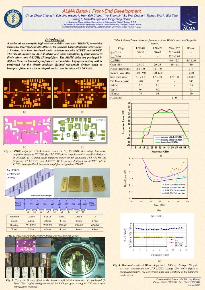
WR22 INPUT WR22 OUTPUT W1 W2 W3 W4 W5 W6 W7 W8 W9 W10 L1 L2 L3 L4 L5 L6 L7 L8 L9 ALMA Band-1 Front-End Development Chau-Ching Chiong ‡,Yuh-Jing Hwang ‡, Hon-Yeh Chang*, Yo-Shen Lin*Su-Wei Chang ‡, Tashun Wei ‡, Wei-Ting Wong ‡, Huei-Wang‡† andMing-Tang Chen‡ ‡: Academia Sinica Institute of Astronomy & Astrophysics, Taipei, Taiwan, R.O.C. *: Department of Electrical Engineering, National Central University, Chung-Li, Taiwan, R.O.C. †: Department of Electrical Engineering, National Taiwan University, Taipei, Taiwan, R.O.C. Introduction A series of metamorphic high-electron-mobility transistor (MHEMT) monolithic microwave integrated circuits (MMICs)for Acatama Large Millimeter ArrayBand-1 Receiver have been developed under collaboration with NTUEE and NCUEE. The circuit include the 31.3-45.0GHz low-noise amplifiers, Q-band balanced diode mixer, and 4-12GHz IF amplifiers. The MMIC chips are packaged in ASIAA Receiver laboratory to form circuit modules. Cryogenic testing will be performed for the circuit modules. Related waveguide devices, such as bandpass filters are also developed under collaboration with NCUEE. Table I. Room Temperature performance of the MMICs measured by probe station. (a) (b) (c) (d) Fig. 1. MMIC chips for ALMA Band-1 receivers, (a) 30-50GHz three-stage low noise amplifier design by NCUEE, (b) 35-55GHz three stage low-noise amplifier designed by NCUEE, (c) Q-band diode balanced mixer for RF frequency 31.3-45GHz, LO frequency 27.3-33GHz and 4-12GHz IF frequency designed by NTUEE. (d) 4-12GHz shunt-feedback low-noise amplifier designed by NTUEE. (a) Size of WR22 : 5.7*2.8*5 mm (W*H*L) *9th-order BPF Design: (b) Fig. 2. Waveguide bandpass filter design and mechanical layout. (c) Fig. 4. Measured results of MMIC chips (a) 31.3-45GHz 3-stage LNA gain at room temperature (b) 31.3-45GHz 3-stage LNA noise figure at room temperature. (c) Conversion gain and isolations of the balanced diode mixer.. Corresponding Person: Dr. Yuh-Jing Hwang Phone: 886-2-33652200, Fax: 886-2-23677849 March 2008 Fig. 3. Cryogenic Testing effort on the devices (left) interior structure of a packaged Q-band LNA (right) configuration of the LNA for gain testing in 20K close cycle refrigerator chamber.


![77-886 Exam Dumps - Get 77-886 Dumps PDF [2018]](https://cdn4.slideserve.com/7920082/microsoft-77-886-exam-mos-sharepoint-2010-dt.jpg)