Download
1 / 26
260 likes | 267 Views
Refrigeration and Heat Pump Systems. Two-phase liquid-vapor mixture. Vapor-Compression Refrigeration Cycle. There are four principal control volumes involving these components: Evaporator Compressor Condenser Expansion valve. Most common refrigeration cycle in use today.

E N D
Two-phase liquid-vapor mixture Vapor-Compression Refrigeration Cycle • There are four principal control volumes involving these components: • Evaporator • Compressor • Condenser • Expansion valve • Most common refrigeration cycle in use today All energy transfers by work and heat are taken as positive in the directions of the arrows on the schematic and energy balances are written accordingly.
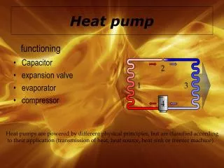
Two-phase liquid-vapor mixture The Vapor-Compression Refrigeration Cycle • The processes of this cycle are Process 4-1: two-phase liquid-vapor mixture of refrigerant is evaporated throughheat transfer from the refrigerated space. Process 1-2: vapor refrigerant iscompressed to a relatively high temperature and pressure requiring work input. Process 2-3: vapor refrigerant condenses to liquid through heat transfer to the cooler surroundings. Process 3-4: liquid refrigerant expands to the evaporator pressure.
The Vapor-Compression Refrigeration Cycle • Engineering model: • Each component is analyzed as a control volume at steady state. • Dry compression is presumed: the refrigerant is a vapor. • The compressoroperates adiabatically. • The refrigerant expanding through the valve undergoes a throttling process. • Kinetic and potential energy changes are ignored.
The Vapor-Compression Refrigeration Cycle • Applying mass and energy rate balances Evaporator (Eq. 10.3) • The term is referred to as the refrigeration capacity, expressed in kW in the SI unit system or Btu/h in the English unit system. • A common alternate unit is the ton of refrigeration which equals 200 Btu/min or about 211 kJ/min.
The Vapor-CompressionRefrigeration Cycle • Applying mass and energy rate balances Compressor Assuming adiabatic compression Condenser Expansion valve Assuming a throttling process (Eq. 10.4) (Eq. 10.5) (Eq. 10.6)
The Vapor-CompressionRefrigeration Cycle • Performance parameters Coefficient of Performance (COP) Carnot Coefficient of Performance This equation represents the maximum theoretical coefficient of performance of any refrigeration cycle operating between cold and hot regions at TCand TH, respectively.
Example 11-1 Refrigerant-134a is the working fluid in an ideal compression refrigeration cycle. The refrigerant leaves the evaporator at -20oC and has a condenser pressure of 0.9 MPa. The mass flow rate is 3 kg/min. Find COPR and COPR, Carnot for the same Tmax and Tmin , and the tons of refrigeration. Using the Refrigerant-134a Tables, we have
The tons of refrigeration, often called the cooling load or refrigeration effect, are
Another measure of the effectiveness of the refrigeration cycle is how much input power to the compressor, in horsepower, is required for each ton of cooling. The unit conversion is 4.715 hp per ton of cooling.
Features of Actual Vapor-Compression Cycle • Heat transfers between refrigerant and cold and warm regions are not reversible. • Refrigerant temperature in evaporator is less than TC. • Refrigerant temperature in condenser is greater than TH. • Irreversible heat transfers have negative effect on performance.
Features of Actual Vapor-Compression Cycle Trefrigerant↑ Trefrigerant↓ through the condenser is increased relative to the temperature of the warm region, TH. • The COP decreases – primarily due to increasing compressor work input – as the • temperature of the refrigerant passing through the evaporator is reduced relative to the temperature of the cold region, TC. • temperature of the refrigerant passing
Features of Actual Vapor-Compression Cycle • Irreversibilities during the compression process are suggested by dashed line from state 1 to state 2. • An increase in specific entropy accompanies an adiabatic irreversible compression process. The work input for compression process 1-2 is greater than for the counterpart isentropic compression process 1-2s. • Since process 4-1, and thus the refrigeration capacity, is the same for cycles 1-2-3-4-1 and 1-2s-3-4-1, cycle 1-2-3-4-1 has the lower COP.
work required in an isentropic compression from compressor inlet state to the exit pressure work required in an actual compression from compressor inlet state to exit pressure Isentropic Compressor Efficiency • The isentropic compressor efficiency is the ratio of the minimum theoretical work input to the actual work input, each per unit of mass flowing: (Eq. 6.48)
Actual Vapor-Compression Cycle State h(kJ/kg) 2s 272.39 2 280.15 3 91.49 4 91.49 1 241.35 Example: The table provides steady-state operating data for a vapor-compression refrigeration cycle using R-134a as the working fluid. For a refrigerant mass flow rate of 0.08 kg/s, determine the (a)compressor power, in kW, (b)refrigeration capacity, in tons, (c)coefficient of performance, (d)isentropic compressor efficiency.
Actual Vapor-Compression Cycle State h(kJ/kg) 2s 272.39 2 280.15 3 91.49 4 91.49 1 241.35 (a) The compressor power is 3.1 kW (b) The refrigeration capacity is 3.41 tons
Actual Vapor-Compression Cycle State h(kJ/kg) 2s 272.39 2 280.15 3 91.49 4 91.49 1 241.35 (c) The coefficient of performance is 3.86
Actual Vapor-Compression Cycle State h(kJ/kg) 2s 272.39 2 280.15 3 91.49 4 91.49 1 241.35 (d) The isentropic compressor efficiency is 0.8 = 80%
p-hDiagram • The pressure-enthalpy (p-h) diagram is a thermodynamic property diagram commonly used in the refrigeration field.
Other Refrigeration Cycles Cascade refrigeration systems Very low temperatures can be achieved by operating two or more vapor-compression systems in series, called cascading. The COP of a refrigeration system also increases as a result of cascading.
Multipurpose refrigeration systems A refrigerator with a single compressor can provide refrigeration at several temperatures by throttling the refrigerant in stages.
Liquefaction of gases Another way of improving the performance of a vapor-compression refrigeration system is by using multistage compression with regenerative cooling. The vapor-compression refrigeration cycle can also be used to liquefy gases after some modifications.
Selecting Refrigerants • Refrigerant selection is based on several factors: • Performance: provides adequate cooling capacity cost-effectively. • Safety: avoids hazards (i.e., toxicity). • Environmental impact: minimizes harm to stratospheric ozone layer and reduces negative impact to global climate change.
Refrigerant Types and Characteristics Global Warming Potential (GWP) is a simplified index that estimates the potential future influence on global warming associated with different gases when released to the atmosphere.
Refrigerant Types and Characteristics • Chlorofluorocarbons (CFCs) and Hydrochlorofluorocarbons (HCFCs) are early synthetic refrigerants each containing chlorine. Because of the adverse effect of chlorine on Earth’s stratospheric ozone layer, use of these refrigerants is regulated by international agreement. • Hydrofluorocarbons (HFCs) and HFC blendsare chlorine-free refrigerants. Blends combine two or more HFCs. While these chlorine-free refrigerants do not contribute to ozone depletion, with the exception of R-1234yf, they have high GWP levels. • Natural refrigerants are nonsynthetic, naturally occurring substances which serve as refrigerants. These include carbon dioxide, ammonia, and hydrocarbons. These refrigerants feature low GWP values; still, concerns have been raised over the toxicity of NH3 and the safety of the hydrocarbons.