Download
1 / 44
600 likes | 1.17k Views
Lecture 4 : Delay Optimization and Logical Effort. Outline. RC Delay Models Delay Estimation Logical Effort Delay in a Logic Gate Multistage Logic Networks Choosing the Best Number of Stages Example s Summary. Delay Definitions. t pdr : rising propagation delay

E N D
Outline • RC Delay Models • Delay Estimation • Logical Effort • Delay in a Logic Gate • Multistage Logic Networks • Choosing the Best Number of Stages • Examples • Summary 5: DC and Transient Response
Delay Definitions • tpdr: rising propagation delay • Max time from input to rising output crossing VDD/2 • tpdf: falling propagation delay • Max time from input to falling output crossing VDD/2 • tpd: average propagation delay • tpd = (tpdr + tpdf)/2 • tr: rise time • From output crossing 0.2 VDD to 0.8 VDD • tf: fall time • From output crossing 0.8 VDD to 0.2 VDD 5: DC and Transient Response
Delay Definitions • tcdr: rising contamination delay • Min time from input to rising output crossing VDD/2 • tcdf: falling contamination delay • Min time from input to falling output crossing VDD/2 • tcd: average contamination delay • tcd = (tcdr + tcdf)/2 5: DC and Transient Response
Simulated Inverter Delay • Solving differential equations by hand is too hard • SPICE simulator solves the equations numerically • Uses more accurate I-V models too! • But simulations take time to write, may hide insight 5: DC and Transient Response
Delay Estimation • We would like to be able to easily estimate delay • Not as accurate as simulation • But easier to ask “What if?” • The step response usually looks like a 1st order RC response with a decaying exponential. • Use RC delay models to estimate delay • C = total capacitance on output node • Use effective resistance R • So that tpd = RC • Characterize transistors by finding their effective R • Depends on average current as gate switches 5: DC and Transient Response
Effective Resistance • Shockley models have limited value • Not accurate enough for modern transistors • Too complicated for much hand analysis • Simplification: treat transistor as resistor • Replace Ids(Vds, Vgs) with effective resistance R • Ids = Vds/R • R averaged across switching of digital gate • Too inaccurate to predict current at any given time • But good enough to predict RC delay 5: DC and Transient Response
RC Delay Model • Use equivalent circuits for MOS transistors • Ideal switch + capacitance and ON resistance • Unit nMOS has resistance R, capacitance C • Unit pMOS has resistance 2R, capacitance C • Capacitance proportional to width • Resistance inversely proportional to width 5: DC and Transient Response
RC Values • Capacitance • C = Cg = Cs = Cd = 2 fF/mm of gate width in 0.6 mm • Gradually decline to 1 fF/mm in nanometer techs. • Resistance • R 6 KW*mm in 0.6 mm process • Improves with shorter channel lengths • Unit transistors • May refer to minimum contacted device (4/2 l) • Or maybe 1 mm wide device • Doesn’t matter as long as you are consistent 5: DC and Transient Response
Inverter Delay Estimate • Estimate the delay of a fanout-of-1 inverter d = 6RC 5: DC and Transient Response
Delay Model Comparison 5: DC and Transient Response
Example: 3-input NAND • Sketch a 3-input NAND with transistor widths chosen to achieve effective rise and fall resistances equal to a unit inverter (R). 2 2 2 3 3 3 5: DC and Transient Response
3-input NAND Caps • Annotate the 3-input NAND gate with gate and diffusion capacitance. 5: DC and Transient Response
Example • Sketch a 2-input NOR gate with selected transistor widths so that effective rise and fall resistances are equal to a unit inverter’s. Annotate the gate and diffusion capacitances. 5: DC and Transient Response
Elmore Delay • ON transistors look like resistors • Pullup or pulldown network modeled as RC ladder • Elmore delay of RC ladder 5: DC and Transient Response
Example: 3-input NAND • Estimate worst-case rising and falling delay of 3-input NAND driving h identical gates. 5: DC and Transient Response
Delay Components • Delay has two parts • Parasitic delay • 9 or 11 RC • Independent of load • Effort delay • 5h RC • Proportional to load capacitance 5: DC and Transient Response
Contamination Delay • Best-case (contamination) delay can be substantially less than propagation delay. • Ex: If all three inputs fall simultaneously 5: DC and Transient Response
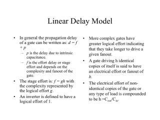
Delay in a Logic Gate • Express delays in process-independent unit • Delay has two components: d = f + p • f: effort delay = gh (a.k.a. stage effort) • Again has two components • g: logical effort • Measures relative ability of gate to deliver current • g 1 for inverter • h: electrical effort = Cout / Cin • Ratio of output to input capacitance • Sometimes called fanout • p: parasitic delay • Represents delay of gate driving no load • Set by internal parasitic capacitance t = 3RC 3 ps in 65 nm process 60 ps in 0.6 mm process 5: DC and Transient Response
Delay Plots d = f + p = gh + p • What about NOR2? 5: DC and Transient Response
Computing Logical Effort • DEF: Logical effort is the ratio of the input capacitance of a gate to the input capacitance of an inverter delivering the same output current. • Measure from delay vs. fanout plots • Or estimate by counting transistor widths 5: DC and Transient Response
Catalog of Gates • Logical effort of common gates 5: DC and Transient Response
Catalog of Gates • Parasitic delay of common gates • In multiples of pinv (1) 5: DC and Transient Response
Example: Ring Oscillator • Estimate the frequency of an N-stage ring oscillator Logical Effort: g = 1 Electrical Effort: h = 1 Parasitic Delay: p = 1 Stage Delay: d = 2 Frequency: fosc = 1/(2*N*d) = 1/4N 31 stage ring oscillator in 0.6 mm process has frequency of ~ 200 MHz 5: DC and Transient Response
Example: FO4 Inverter • Estimate the delay of a fanout-of-4 (FO4) inverter Logical Effort: g = 1 Electrical Effort: h = 4 Parasitic Delay: p = 1 Stage Delay: d = 5 The FO4 delay is about 300 ps in 0.6 mm process 15 ps in a 65 nm process 5: DC and Transient Response
Multistage Logic Networks • Logical effort generalizes to multistage networks • Path Logical Effort • Path Electrical Effort • Path Effort 5: DC and Transient Response
Multistage Logic Networks • Logical effort generalizes to multistage networks • Path Logical Effort • Path Electrical Effort • Path Effort • Can we write F = GH? 5: DC and Transient Response
Paths that Branch • No! Consider paths that branch: G = 1 H = 90 / 5 = 18 GH = 18 h1 = (15 +15) / 5 = 6 h2 = 90 / 15 = 6 F = g1g2h1h2 = 36 = 2GH 5: DC and Transient Response
Branching Effort • Introduce branching effort • Accounts for branching between stages in path • Now we compute the path effort • F = GBH Note: 5: DC and Transient Response
Multistage Delays • Path Effort Delay • Path Parasitic Delay • Path Delay 5: DC and Transient Response
Designing Fast Circuits • Delay is smallest when each stage bears same effort • Thus minimum delay of N stage path is • This is a key result of logical effort • Find fastest possible delay • Doesn’t require calculating gate sizes 5: DC and Transient Response
Gate Sizes • How wide should the gates be for least delay? • Working backward, apply capacitance transformation to find input capacitance of each gate given load it drives. • Check work by verifying input cap spec is met. 5: DC and Transient Response
Example: 3-stage path • Select gate sizes x and y for least delay from A to B 5: DC and Transient Response
Example: 3-stage path Logical Effort G = (4/3)*(5/3)*(5/3) = 100/27 Electrical Effort H = 45/8 Branching Effort B = 3 * 2 = 6 Path Effort F = GBH = 125 Best Stage Effort Parasitic Delay P = 2 + 3 + 2 = 7 Delay D = 3*5 + 7 = 22 = 4.4 FO4 5: DC and Transient Response
Example: 3-stage path • Work backward for sizes y = 45 * (5/3) / 5 = 15 x = (15*2) * (5/3) / 5 = 10 5: DC and Transient Response
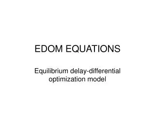
Best Number of Stages • How many stages should a path use? • Minimizing number of stages is not always fastest • Example: drive 64-bit datapath with unit inverter D = NF1/N + P = N(64)1/N + N 5: DC and Transient Response
Derivation • Consider adding inverters to end of path • How many give least delay? • Define best stage effort 5: DC and Transient Response
Best Stage Effort • has no closed-form solution • Neglecting parasitics (pinv = 0), we find r = 2.718 (e) • For pinv = 1, solve numerically for r = 3.59 5: DC and Transient Response
Review of Definitions 5: DC and Transient Response
Method of Logical Effort • Compute path effort • Estimate best number of stages • Sketch path with N stages • Estimate least delay • Determine best stage effort • Find gate sizes 5: DC and Transient Response
Limits of Logical Effort • Chicken and egg problem • Need path to compute G • But don’t know number of stages without G • Simplistic delay model • Neglects input rise time effects • Interconnect • Iteration required in designs with wire • Maximum speed only • Not minimum area/power for constrained delay 5: DC and Transient Response
Example 1 Calculate the • a) logical effort • b) parasitic delay • c) effort and • d) delay in the following 6-input AND implementations as a function of the path electrical effort H. Which implementation is the fastest if a) H=1, b) H=5 and c) H=20? 5: DC and Transient Response
Example 2 • For the path between x and F in the following circuit calculate: • a. Total delay • b. Path effort and parasitic delay • c. minimum theoritical delay 5: DC and Transient Response
Summary • Logical effort is useful for thinking of delay in circuits • Numeric logical effort characterizes gates • NANDs are faster than NORs in CMOS • Paths are fastest when effort delays are ~4 • Path delay is weakly sensitive to stages, sizes • But using fewer stages doesn’t mean faster paths • Delay of path is about log4F FO4 inverter delays • Inverters and NAND2 best for driving large caps • Provides language for discussing fast circuits • But requires practice to master 5: DC and Transient Response