Download
1 / 98
980 likes | 1.08k Views
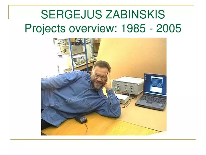
SERGEJUS ZABINSKIS Projects overview: 1985 - 2005. INTRODUCTION.

E N D
INTRODUCTION I graduated Mathematics Faculty of Vilnius State University in 1985. As almost all students at that time I gained fundamental mathematics background from algebra and calculus to functional analysis and topology. Also I gained a good background in numerical computational methods that helped me much in my work. All my work experience is very close to computer programming. I hope that this slide show that contains some of the projects where I have been participating as a member of team or alone will give you additional information about me.
IMAGE PROCESSING Years: 1990-1992
Image processing algorithms and techniques • In the beginning of 1990s I was a member of an image processing initiative group, the objective of which was to acquire information on image processing methods and its applications. Here I got to know the main image processing techniques such as: • Fast linear box filtering • Fast median filtering based on T.Huang algorithm • Histogram equalization • Local histogram equalization • Image binarization methods • Binary image skeletonization • Contour extraction • Contour tracing • Component labeling • Hough transformation This experience helped me much in other projects.
Example of image preprocessing techniques Extracted and thinned contours of original image. Original halftone image
Example of image preprocessing techniques Preprocessed image (histogram equalization procedure applied) Original halftone image
DRIVING THEORY TEST PROGRAM Company: ALS Years: 1994
Geometric modeling language • In 1994 I was hired by company “ALS” to develop driving theory test program. The main problem was to prepare program questionnaire that reached 500 questions, most of them contained graphics. • To do that I invented a simple programming language to deal with 2D graphics objects such as • lines, • rectangles, • polygons, • circles, • ellipses, etc • Language also has the set of transformations - reflections, rotations, translations, scaling transformation. With the help of this language it is possible to encode complex enough graphic object such as road signs and symbolic situations on the road. I implemented language parser that converted source code to byte-code and engine to execute byte-code. Important to note that this approach let me do very compact questionnaire – it was very significant in the 1994.
Geometric primitives Since project was implemented with Turbo C compiler, all graphic object directly correspond to graphics objects that were supported by BGI graphics: arc circle ellipse fillellipse fillpoly line outtext outtextxy pieslice putpixel rectangle sector setcolor setfillpattern setfillstyle setlinestyle
Examples of language constructions COLOR(WHITE) TRANSLATE (45,30) { REFLECTY() { ROTATE (45) POLYGON (7,-15,70,-15,-70,-40,-70,0,-140,40,-70,15,-70,15,70) } } This code snippet means that color of pen is set to white. After that we: • rotate polygon to 45 degrees; • apply reflection transformation for rotated polygon; • finally translate it.
Example of real graphic object implemented using geometric modeling language
Source code (1) #include "TRIS.PIC" COLOR (BLACK) FILLSTYLE (SOLID_FILL,BLACK) // // BUDKA // TRANSLATE (45,2) { FRECT (-20,-30,20,30) // WINDOW COLOR (WHITE) FILLSTYLE (SOLID_FILL,WHITE) TRANSLATE (0,-10) FRECT (-10,-10,10,10) COLOR (BLACK) FILLSTYLE (SOLID_FILL,BLACK) // KRYSHA TRANSLATE (2,-25) FRECT (-22,-5,22,5) } // KOTEL TRANSLATE (-30,13) { POLYGON (7,-50,0,50,0,50,-20,-40,-20,-45,-15,-48,-10,-49,-5) REFLECTX () POLYGON (7,-50,0,50,0,50,-20,-40,-20,-45,-15,-48,-10,-49,-5) }
Source code (2) // Chimney TRANSLATE (-55,-17) FRECT (-7,-10,7,10) // FUNDAMENT TRANSLATE (-5,45) FRECT (-72,-10,72,10) // BUMPER TRANSLATE (-75,50) FRECT (-10,-10,10,10) // Wheels TRANSLATE (-50,55) { COLOR (BLACK) FILLSTYLE (SOLID_FILL,BLACK) FILLCIRCLE (0,0,15) COLOR(WHITE) FILLSTYLE (SOLID_FILL,WHITE) FILLCIRCLE (0,0,12) } TRANSLATE (-10,55) { COLOR (BLACK) FILLSTYLE (SOLID_FILL,BLACK) FILLCIRCLE (0,0,15) COLOR(WHITE) FILLSTYLE (SOLID_FILL,WHITE) FILLCIRCLE (0,0,12) }
Source code (3) TRANSLATE (30,55) { COLOR (BLACK) FILLSTYLE (SOLID_FILL,BLACK) FILLCIRCLE (0,0,15) COLOR(WHITE) FILLSTYLE (SOLID_FILL,WHITE) FILLCIRCLE (0,0,12) } // DISKS TRANSLATE (-50,55) { COLOR (BLACK) FILLSTYLE (SOLID_FILL,BLACK) FILLCIRCLE (0,0,5) COLOR (WHITE) FILLSTYLE (SOLID_FILL,WHITE) FILLCIRCLE (0,0,2) } TRANSLATE (-10,55) { COLOR (BLACK) FILLSTYLE (SOLID_FILL,BLACK) FILLCIRCLE (0,0,5) COLOR (WHITE) FILLSTYLE (SOLID_FILL,WHITE) FILLCIRCLE (0,0,2) }
Source code (4) // // SMOKE // COLOR (BLACK) FILLSTYLE (SOLID_FILL,BLACK) TRANSLATE (0,-115) FILLCIRCLE (0,0,12) TRANSLATE (0,-90) FILLCIRCLE (0,0,20) TRANSLATE (-20,-70) FILLCIRCLE (0,0,16) TRANSLATE (-55,-30) PIESLICE (0,0,0,180,6) TRANSLATE (-50,-40) FILLCIRCLE (0,0,6) TRANSLATE (-40,-45 ) FILLCIRCLE (0,0,8) TRANSLATE (-30,-50 ) FILLCIRCLE (0,0,10) TRANSLATE (-25,-55) FILLCIRCLE (0,0,10) TRANSLATE (-30,-60 ) FILLCIRCLE (0,0,10)
Example of graphic object implemented using geometric modeling language
SIGNAL MEASUREMENT SYSTEM BASED ON RK2-01 Company: INMATSIS Years: 1997
Acquired signal marker measurement Acquired signal may be measured by markers, saved to database and printed.
Main parameters summary for acquired signal Also program can estimate main parameters: peak-to-peak amplitude, amplitude, period, rise/fall times, impulse duration.
Signal database browser Each signal may be retrieved from database to continue its investigation, exported to text file, printed and removed from database.
COMPENSATION OF WIDE-ANGLE OBJECTIVE OPTICAL DISTORTIONS Company: INMATSIS Years: 1998
Calibration transformation for wide-angle objective This work was performed as part of signal registration research project. We used camera to get image directly from the screen of analogue measurement device. Here I used measurement grid images (graticule) to create calibration transformation to compensate wide-angle objective optical distortions.
Illustration of calibration transformation Original image Transformed image with compensated fish-eye objective distortions
Illustration of calibration transformation Transformed image with compensated objective distortions. Original image
NUMERICAL ALGORITHMS APPLICATIONS Company: INMATSIS Years: 1996-2000
HIGH SPEED NONREPETITIVE SIGNALS REGISTRATION SYSTEM K2-74 Company: INMATSIS Years: 2001-2002
K2-74 view • K2-74 is the measurement system for registration of nonrepetitive and periodic signals in nanosecond and picosecond range. The main parts of system: • Analogue measurement device; • Camera; • Framegrabber; • PC (interfaces: IEEE-488 or RS-232).
Image preprocessing (why needed) We get noisy images while catching high speed signals. You can see many speckles on the image.
Image preprocessing (median filter) To eliminate speckles we use median filter. In this program we implemented fast median filter. It processes images in real time.
Image preprocessing (speckles suppression) Sometimes speckles always present on the screen. It may be caused by tube defect. In this case we simply put “black” circle over the speckle.
Image preprocessing (Region Of Interest) Sometimes it is useful to process only part of the screen. We call it region of interest. It can fasten image processing and as we see here it can leave speckles outside.
Image preprocessing (image averaging for repetitive signals) Averaging along the sequence of 10 images Single image
Accurate signal extraction • We used two ways to extract signal points from raster image: • mass center method • pixel distribution approximation using Gaussian function. • The first way is very fast but not accurate. And the second way is very accurate but needs more CPU time (nonlinear optimization problem is solved for each point of signal trace section). • Here is the illustration of pixel distribution peak estimation using the second way.
Comparison of two ways of signal extraction Blue signal is extracted using mass center method Green signal is extracted using Gaussian approximation method
Calibration grid Example of calibration grid that is used to build calibration transformation for time/div= 10 ns.