Download

1 / 14
140 likes | 223 Views
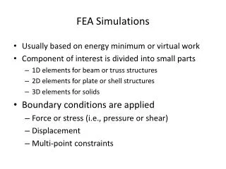
Ahmad Shahwan Jean-Claude Léon Gilles Foucault ROMMA status briefing December 2012. From CAD to FEA through functional annotations. Overview. Workflow Reminder From Global Coordinate Systems to Local Coordinate Systems Limitations of Global CS Adopting Local CS

E N D
Ahmad Shahwan Jean-Claude Léon Gilles Foucault ROMMA status briefingDecember 2012 From CAD to FEA through functional annotations
Overview Workflow Reminder From Global Coordinate Systems to Local Coordinate Systems Limitations of Global CS Adopting Local CS Screw Addition/Subtraction Local CS and Internal Forces Cycles Indeterminate Static Equilibrium New Results
Limitation of Global CS Global CS Interface CS (3.5 DoF) (2 DoF) + + (0 DoF) (1 DoF) • Studying the nut equilibrium: • Using Global CS Spline connection is valid! • Using Interface CS Spline connection is invalid. = =
Choosing Local CS • To enable summation of screws: • CS should be unified over components interfaces. • CS for each component; • Chosen amongst those of its interfaces. Two interfaces with the same CS Two interfaces with different CS’s
Adopting Local CS • Previously, mech. screws were expressed according to one global CS. • Now, screws are associated with there own CS. • For static equilibrium analysis, same principals hold. • need to unify B.
LCS & Internal Force Cycles 1 • Originally internal forces where projected on each axis of the GCS Graph of force propagation. • This is not possible any more! 5 2 4 3 z y x z
LCS & Internal Force Cycles 1 • Generate force propagation graph independently from CS. • Currently, we only propagate forces between contacts and threads; • Advantage: force propagates in one direction through theses interfaces. • Disadvantages: not general enough! • Detecting propagation direction at threaded links. 5 2 4 3
LCS & Internal Force Cycles • Example of cylindrical washer elements. • Here internal forces propagate through shaft/bushing link. • Problem with this kind of interfaces is that they defuse internal forces in more than one direction!
Indeterminate static equilibrium • Indeterminate static (hyperstatic) equilibrium may be functional, or may indicate anomaly. • Nut/counter-nut tightening is an example of functional hypestatic configurations. • Indeterminism is used here to increase internal system energy. • Incorrect interpretation of tight fit produces an erroneous hyperstatic equilibrium. • This may helps the elimination of irrelevant interpretations.
Indeterminate static equilibrium Isostatic Hyperstaticas a result of detection error Hyperstaticfunctional 3 1 2 2 3 1
New Results • Manipulating the way facts are submitted. • Adding new rules. • Recognition of new components • Distinction between nuts and counter-nuts in the root