Download

1 / 26
280 likes | 460 Views
Avidyne SR-22 Electrical System. Electrical System. 28 Volt DC Negative Ground Dual Alternator Dual Battery The system provides uninterrupted power for the avionics, flight instrumentation, lighting, and other electrically operated and controlled systems during normal operation. Components.

E N D
Electrical System • 28 Volt DC • Negative Ground • Dual Alternator • Dual Battery • The system provides uninterrupted power for the avionics, flight instrumentation, lighting, and other electrically operated and controlled systems during normal operation.
Components • Alternator 1 • 100/60 Amp (60 amp no A/C) • 28 Volts • Gear driven • Internally rectified • Self exciting (requires battery voltage for field excitation in order to start operating) • Powers Main Distribution bus directly and Essential Bus indirectly *Click on diagram above to see actual picture of component
Components • Alternator 2 • 20 Amp • 28.75 Volts • Gear Driven • RPM dependant < 1700 rpm it will not work • Internally rectified • Self exciting (requires battery voltage for field excitation in order start operating) • Powers Essential Bus • Cannot power Main Distribution Bus (diodes) *Click on diagram above to see actual picture of component
Components • Battery 1 • Aviation grade 12-cell • 24-Volt • 10 amp-hour • Mounted on right side of firewall • Charged by Alt 1 through Main Dist Bus • Can supply power to the Main and Essential Distribution Buses *Click on diagram above to see actual picture of component
Components • Battery 2 • Two 12 volt batteries in series = 24 volts total • 7 amp-hour • Sealed lead acid • Located in the tail of the airplane below the parachute canister • Charged by Alt 1 or Alt 2 from a circuit breaker on the Essential Distribution Bus • Powers Essential Dist Bus only due to isolation diodes *Click on diagram above to see actual picture of component
Components • Master control Unit (MCU) • Controls: ALT 1, ALT 2, starter, landing light, external power and generation functions • Provides: • ALT 1 and ALT 2 voltage regulation and overvoltage protection • External power reverse polarity protection • Electrical health annunciations to the Integrated Avionics System *Click on diagram above to see actual picture of component
Components • Isolation Diodes • Electrical “check valves” or “one way street” • Electricity can only flow in the direction of the arrows • Prevent ALT 2 from powering the Main Dist Bus • Prevent BAT 2 from powering the Main Dist Bus • Check operation of diodes during preflight by turning only BAT 2 on and then verifying flap position light is out
Controls • Electrical System Control • Master Switches • Rocker type electrical system master switches are located in front of the pilot on the bolster panel for easy access. • Circuit Breaker Panel • Located on left side of center console • Alternating gray collars on the CB panel provides easier recognition of circuit breakers • Circuit breakers are re-settable (once)
Normal Operations • ALT 1-28 volts • Supplies power to Main Dist Bus • Charges BAT 1 • Powers Essential Bus when aircraft is < 1700 rpm • ALT 2- 28.75 volts • Supplies power to the EssBus during cruise flight (>1700 rpm) because it operates at a higher voltage • Water analogy- Think of higher voltage as higher pressure (water) running through the wires (pipes). The higher voltage (pressure) of ALT 2 prevents ALT 1 from powering the Ess Bus • Charges BAT 2 • Diodes prevent ALT 2 from powering the Main Dist Bus • Click on diagram to see “normal” engine indications *Click on diagram above to see normal engine indications during flight
Abnormal Operations ALT 1 Failure Steady “ALT 1” annunciator panel Verify on MFD engine page or ampere meter switch ALT 1 (A)- 0 ALT 2 (A) - Normal BATT 1 (A) discharging -12 How long will it last? How to reduce drain on BATT 1? Ess (V)- 28.7 ALT 2 Main (V)- 24.2 Bat1 ALT 1
Abnormal Operations • ALT 1 failure • BAT 1 powers Main Bus items • Turn off these items to reduce discharge of BATT 1 if ALT 1 fails • Some items on the main bus have a primary circuit breaker on the Ess bus (#1). These items will be powered by ALT2 through the Ess Bus (higher voltage) • Turn coordinator (hidden behind right bolster panel to provide roll information to the autopilot) • Attitude indicator • HSI/PFD • ALT 2 continues to power Ess Bus items • Complete ALT 1 failure checklist to attempt reset of ALT 1
Abnormal Operations ALT 2 Failure Steady “ALT 2” on annunciator panel Verify on MFD engine page or ampere meter switch ALT 1 (A)- 12 Normal ALT 2 (A) - 0 BATT 1 (A) Normal Ess (V)- 28- Alt1 Main (V)-28- Alt1
Abnormal Operations • ALT 2 Failure • < 1700 RPMS ALT 2 will not work • ALT 1 will power the entire electrical system • Follow ALT 2 failure checklist and try to reset ALT 2 • ALT 2 is required for IFR flight
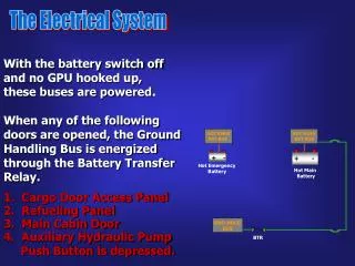
Ground Service Receptacle • Allows connection of an External Power Unit for cold weather starting and maintenance • BAT 1 switch must be on to deliver power to system • BAT 1 must have power for the contactor to close • Recharging of BAT 1 should not be accomplished through use of an External Power Unit • External Power Unit voltage must be regulated to no higher than 28 VDC
Question • During the preflight check, why do we initially turn BAT 2 on only? • Allows the pilot to check voltage (health) of BAT 2 • To verify the isolation diodes are operating correctly- flap light out
Scenario • During the preflight check with only BAT 2 on, you noticed the flap light was on. Would you still depart for your flight? Why or why not? • The isolation diodes are not working correctly. ALT 2 would then try to power the entire electrical system. ALT 2 is 20 amps and not powerful enough to power Main Dist Bus items. This most likely, will cause ALT 2 to fail • The pilot would be unable to isolate items on the Essential Dist Bus in an emergency. BAT 2 would try to the power Main Distribution Bus.
Scenario • Looking at your engine data in cruise, this is what you see. Has anything failed? What are you going to do? • ALT 1 has failed. Perform ALT 1 failure checklist.
Scenario • Looking at your engine data in cruise, this is what you see. Has anything failed? What are you going to do? • ALT 2 has failed. Perform ALT 2 failure checklist.
Scenario You are 30 minutes out from your destination and you begin to smell something. After investigating you see white smoke rising from the circuit breaker panel. What is happening? What will you do? Will your procedure be different in VMC vs. IMC? Day vs. Night?
Bat 1 Alt 1 Alt 2 Main Distribution Bus Essential Distribution Bus 2.2 Cont. ● Landing Light Main Bus 2 Essential Bus 1.00 Cont. ● Fuel Pump ● Turn Coordinator # 2 ● Attitude # 2 ● HSI / PFD # 2 ● ALT 1 0.32 Cont. ● O2 / Cabin Lights Non-Essential Avionics ● Annun / Engine Inst ● Turn Coordinator # 1 ● Attitude # 1 ● HSI / PFD # 1 ● Stall Warning ● Battery 2 Essential Power Bat 2 1.45 Cont. ● Skywatch / TAWS 1.12 Cont. ● GPS 2 1.74 Inter. ● Com 2 1.14 Cont. ● Encoder / xponder 0.63 Cont. ● XM / Stormscope 2.25 Cont. ● MFD 0.36 Cont. ● Audio Panel ● Starter Relay 3.60 Cont. ● Pitot Heat / 0.23 Cont. ○ Cooling Fan 3.00 Cont. ● 12VDC outlet 4.20 Cont. ● Strobe Lights 3.98 Cont. ● Nav Lights 6.50 Inter. ● Flaps ● Autopilot Avionics Non-Essential Avionics 0.36 Cont. ● Fuel Qty / Hobbs 1.11 Cont. ● Inst. Lights 0.30 Inter. ● Pitch Trim 0.75 Inter. ● Roll Trim 1.50 Cont. ● Ice Protection ● Com 1 ● GPS 1 Essential Avionics Non-Essential Bus Main Bus 1 11.3 Cont. ● Condenser 9.20 Cont. ● Fan 1.96 Cont. ● Compressor / Control A/C 1 A/C 2