Download
1 / 39
390 likes | 552 Views
International Linear Collider DR electron cloud R&D effort 1 st part: Tests in PEP-II. M. Pivi L. Wang, D. Arnett, G. Collet, R. Kirby, F. King, T. Markiewicz, B. McKee, M. Munro, N. Phinney, T. Raubenheimer, J. Seeman (SLAC), F. Le Pimpec (PSI) ECLOUD 07

E N D
International Linear Collider DR electron cloud R&D effort1st part: Tests in PEP-II M. Pivi L. Wang, D. Arnett, G. Collet, R. Kirby, F. King, T. Markiewicz, B. McKee, M. Munro, N. Phinney, T. Raubenheimer, J. Seeman (SLAC), F. Le Pimpec (PSI) ECLOUD 07 Daegu S. Korea
ILC DR Electron cloud simulation history • Effort started in 2003 with extensive simulations of electron cloud build-up in DR including quadrupole and wigglers regions, and simulations to characterize the single-bunch instability threshold • International collaboration R&D effort: 2005-2006 simulation campaign culminating in the recommendation for the damping ring circumference reduced from 17 km to 12km [electron cloud safe], then further reduced to 6km [red flag for electron cloud]. • Although an electron cloud is expected in the 6km positron Damping Ring, simulations give increased confidence on possible remedies as clearing electrodes and grooves. • Substantial R&D effort is needed to confirm possible mitigation techniques.
Compare options: simulations history Cloud density near (r=1mm) beam (m-3) before bunch passage, values are taken at a cloud equilibrium density. Solenoids decrease the cloud density in DRIFT regions, where they are only effective. Compare options LowQ and LowQ+train gaps. All cases wiggler aperture 46mm.
Global ILC R&D program In progress: - At KEKB:in situ Secondary Electron Yield (SEY) measurements, ante-chamber, Cu, TiN and NEG chambers. PLANNED: Clearing electrodes in wiggler. - At SLAC: SEY of samples in accelerator beam line, rect. groove chambers, TiN chambers. PLANNED: Clearing electrodes and grooves in bends. Planned: - SPS and PS: LHC pre/injectors. Scrubbing runs and several mitigation techniques are under evaluation. - Daphne: positron ring limited in current. TiN in aluminum wiggler sections. Proposed: - CesrTA: suppression techniques in wigglers (ILC damping ring wigglers). Electron cloud build-up and instability with ultra-low emittancies close to the ILC DR. - KEKB: Low emittance operation for electron cloud tests
E-cloud and SEY R&D Program SLAC • R&D Goals: • Estimate e-cloud build-up and single-bunch instability thresholds • Reduce surface secondary electron yield (SEY) below electron cloud threshold for ILC DR: SEY ≤ 1.2 • Surface approaches • Thin film coatings • Electron and photon surface conditioning • Clearing electrodes • Grooved surfaces • Projects: • ONGOING: conditioning TiN and NEG coatings in PEP-II straights • ONGOING: rectangular groove chambers in PEP-II straights • PLANNED: clearing electrode chamber in magnets • PLANNED: triangular groove chamber in magnets
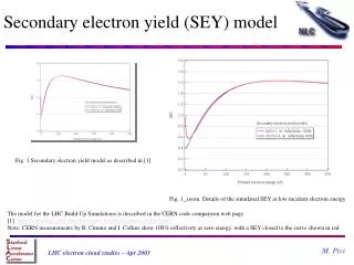
SEY GROOVE 1 FLAT 1 GROOVE 2 FLAT 2 ENERGY ANALYZER COLLECTORS THERMOCOUPLES PEP-II test chambers installation SEY TEST STATION GROOVE CHAMBERS EXPERIMENT SEY station can be used to expose samples to PEP-ii beam environment and then measure samples in lab (transport in load-lock) Grooved and Flat chambers installed to measure performance inPEP-ii beam environment
SEY TESTS TiN and NEG • Expose samples to PEP-II LER synchrotron radiation and electron conditioning. Then, measure Secondary Electron Yield (SEY) in laboratory. Samples transferred under vacuum. RF seal location PEP-II LER side 20mm TiN/Al sample exposed to SR Complementary at SPS and KEK studies
Project 2: chamber with coating samples. PEP-II e+ sample supports and transferring systems 0o position 45o position
SEY test station in PEP-II LER 0o position 45o position
SEY test station in PEP-II LER 0o position 45o position
SEY chamber instrumentation: e- energy analyzer R. Kirby and M. P. SLAC, based on K.Harkay and R.Rosenberg design
Design- Fin Extrusions FAN EVENTUALLY HITS “BOTTOM” OF SLOT FOR FULL SR STRIKE LIGHT PASSES THRU SLOTS BETW FINS BECAUSE FAN IS “THICKER” THAN FIN FIN TIPS= I.D. OF CHAM FAN HITS HERE FIRST VIEW IS ROTATED 90 CCW FROM ACTUAL FAN ORIENTATION p.14
Design- Fin Chamber • Chambers are constructed of Al extrusions machined to length with end preps for masks & flanges. • Al extrusions were chosen for their economy and ease of manufacture • Bonus - cooling is integral to the cross section, not welded to the outside • Flanges are bi-metal Atlas flanges that are welded directly to chamber • Insufficient space between the chamber and the flange knife edge for a bi-metal transition • Bottom sides of chambers are perforated at the ports • Inside surfaces are TiN coated • Reduce thermal outgassing & PSD • Reduce secondary electron yield • Fin chamber weight ~ 32 lbs p.15
Design- Port Detail • 4” port shown here, 500 holes, 25 x 20, holes 1.6 mm • 1.5” port hole pattern is 50 holes, 10x5, holes 1.6 mm p.16
Chamber samples: SEY after TiN coating before installation in PEP-II
Installation in PEP-II LER Flat chamber Fin chamber
Design – Existing Ring Layout LER DIRECTION PLAN VIEW AISLE SIDE ELEVATION VIEW TIN/Al GROOVE/FLAT CHAMBERS HERE SEY CHAMBER HERE BEND B1 p.20
SEY test chamber samples: SEY before installation in PEP-II LER #1 and #2 samples are then inserted in the PEP-II stainless steel chamber respectively in the plane of the synchrotron radiation fan (0o position) and out of this plane (45o position)
Surface analysis: Carbon content decrease XPS Before installation After exposure in PEP-II LER for 2 months (e dose 100mC/mm^2) LER#1 Different from electron conditioning in laboratory setup where carbon crystals grows! Carbon is strongly reduced if exposed to beam. Same for LER #1 and #2 samples.
SEY after exposure to vacuum After 2 months conditioning in PEP-II +214 hours at 1.1e-9 torr, 10:1 H2:CO (214 = 52 hours in PEP-II no beam +162 in laboratory setup)
Compare vacuum chamber e- currents 18 March 2007 groove1 groove2 flat2 flat1 Measured e- current in TiN/Al fin/flat chambers << StSt chamber. PEP-II LER current still raising (2.7A 4A).
Solenoid ON at fin/flat chambers location Switched external solenoid winding ON (10A Bz=20 Gauss). Ibeam = 2.2A. Note: at ~20 Gauss, photoelectrons should dominate with respect to secondary electrons..
Preliminary benchmark with CLOUDLAND L.Wang SLAC In simulation, the SEY and the number of photon electrons are varied For the Flat chamber, the SEY is around 1.1~1.2 Flat 2 Flat 1
Flat chamber This plot only show the SEY effect, R=0.001 for all of them (R=e/p/m) Simulation: - Uniform photoe- distribution - Electron current at the wall
Grooved chamber For the grooved chamber, the SEY is ~1 Simulation: - Uniform photoe- distribution - Electron current at the wall
SEY estimation Grooved Chamber has more photon electrons for some reason, but Flat Chamber has more secondary electrons, hence a higher SEY. This agree with simulation. Raw data Ratio of Secondary to photoelectrons Total electrons
New Model PEPII Exp. • Simulation closer to the experimental setup: • - Photo e- on the chamber side • Collector on bottom chamber • Need more detail study KEKB Exp. Y. Suetsugu, APAC07
Work in progress • Electron signal in flat & fin chambers is much lower than stainless steel chamber. • Electron signal in flat chambers is lower than fin chambers: • Photoelectron dominant in fins? • Fin chambers efficient photon absorbers? • Simulation campaign starting: • Fitting stainless steel data to parameterize SEY • Fitting to flat & fin chamber data: • Low SEY in flat chambers and grooved chambers between 0.9~1.2 • Appear to have higher photo e- rate in fin chambers • Need ray tracing of photons to understand fin chamber More input would be welcome
Plan for future work Simulations: • Systematic simulation effort starting • Further code benchmarking will be done Experimental • Conditioning and recontamination studies • Insertion in beam line of non-evaporable getter NEG samples • Insertion of samples with different materials: Cu, Stst, Al • Study asymptotic conditioning effect: coating the stainless steel chamber with TiN (and NEG). • Testing of chambers with NEG and clearing electrodes
Outstanding e-cloud questions Simulations • Are the build-up codes sufficiently developed and benchmarked? • Are the instability code sufficiently developed and benchmarked? • What is the SEY threshold in the ILC DR configuration 3ns bunch spacing? • More code benchmarking needed • In the presence of an electron cloud: is the dynamic aperture preserved at injection? • Large beam sizes no instability, but incoherent tune shift, .. • Incoherent emittance growth below threshold, is it a real effect? Remedies • Is TiN thin film resistant after long term exposure? • How to minimize vacuum recontamination (SEY) effects? • What coating: TiN or NEGs (TiZrV) • Do we need ultra-small emittance facilities to run electron cloud tests? CesrTA/KEKB • Dependence of the SEY with NEG activation cycles? (highly requested by CERN!) • Do we need to test clearing electrodes to suppress the electron cloud? • Is TiN coating sufficient in wigglers? • Measured trapping and accumulation of electrons in quadrupoles (sextupoles)? Is this an issue per se?
Milestones to the ILC Engineering Design Report (EDR) • 1. Characterize electron-cloud build-up. (Very High Priority) • 2. Develop electron-cloud suppression techniques. (Very High Priority) • Priority: characterize coating techniques and testing of conditioning and recontamination in situ. • Clearing electrodes concepts by installation of chambers in accelerators. Characterization of impedance, HOM and power load deposited to the electrodes. • Groove, slots and other concepts. Characterization of impedance, and HOM. • 3. Develop modeling tools for electron-cloud instabilities. (Very High Priority) • 4. Determine electron-cloud instability thresholds. (Very High Priority) • Characterization the electron cloud instability: various codes in use PETHS, HEAD-TAIL, WARP/POSINST, CMAD
Summary • Installed 5 chambers in PEP-II in January 2007 • Directly measured secondary electron yield of ~0.9 of TiN samples after exposure to beam. [Steering the ILC R&D effort in the direction of fully characterizing coating mitigation techniques..] • Recontamination studies ongoing • Electron signal in Fin & Flat chambers is much lower than stainless steel chamber • Initial simulations: consistent with high SEY in Stainless steel chamber and low SEY in Fin & Flat TiN/Al chambers • Systematic simulation effort ongoing to parameterize fin & flat chambers results
Thanks To contributors and collaborators: L. Wang, T. Raubenheimer, D. Arnett, G. Collet, R. Kirby, N. Kurita, B. Mckee, M. Morrison, G. Stupakov, N. Phinney, J. Seeman (SLAC), M. Palmer, D. Rubin, D. Rice, L. Schachter, J. Codner, E. Tanke, J. Crittenden (Cornell), J. Gao (HIPEP), A. Markovic et al. (Rostock Univ.), M. Zisman, S. De Santis, C. Celata, M. Furman, J.L. Vay, S. De Santis (LBNL), K. Ohmi, Y. Suetsugu (KEK), F. Willeke, R. Wanzenberg (DESY), J.M. Laurent, A. Rossi, E. Benedetto, F. Zimmermann, G. Rumolo, J.M. Jimenez, J-P. Delahaye (CERN), A. Wolski (Cockroft Uniiv.), B. Macek (LANL), C. Vaccarezza, S. Guiducci, R. Cimino, P. Raimondi (Frascati), et many other colleagues…