Download
1 / 20
200 likes | 379 Views
CEEN 572 Environmental Engineering Pilot Plant Laboratory . Introduction to the Mini -Pilot Treatment System. Mini -Pilot Treatment System. Mimics both conventional and direct filtration plant Direct filtration skip sedimentation Appropriate for low-turbidity source water

E N D
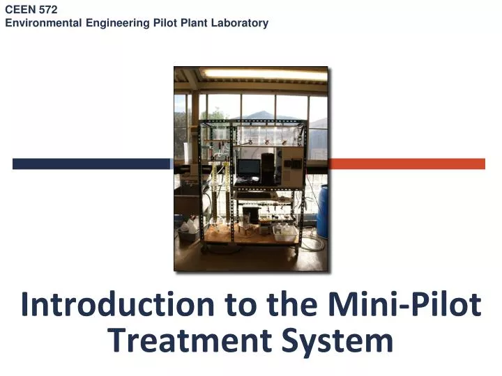
CEEN 572Environmental Engineering Pilot Plant Laboratory Introduction to the Mini-Pilot Treatment System
Mini-Pilot Treatment System • Mimics both conventional and direct filtration plant • Direct filtration skip sedimentation • Appropriate for low-turbidity source water • The min-pilot mimics CSM’s pilot system at the Golden WTP • Partially automated treatment system • Critical operating steps • Startup • Backwashing • Dose adjustments • Data retrieval
Dual-Media Filter • Anthracite coal (1.55) and quartz sand (2.65) • More depth is utilized
Anthracite 0.5 – 2 mm
Headloss Through Clean Granular Filters • Net available head = filter design headloss – clean-bed headloss • Insignificant in slow sand and pre-coat filtration, but important in rapid filtration
Rapid Filtration – Filter Run • Effluent turbidity characterized by three distinct segments: • Ripening • media conditioning (15 min - 2 hr) • Sometimes contain two peaks • Size and duration can be reduced by proper backwashing procedure • Filter-to-waste line • Effective filtration • Steady state turbidity <0.1 NTU • Gradual increasing in head loss • Breakthrough • Filter can’t hold more particles • Effluent turbidity increases • Headloss increases
Rapid Filtration – End of Filter Run • Can be triggered by several events and lead to backwash: • Breakthrough • Headloss • Increases beyond the available head through the process • Rapid filters are typically designed with 1.8-3 m (6-10 ft) available head • If in specific cases neither are reached within several days: utility initiate backwash after a set period of time
pH adjustment Backwash Waste Chlorine V-2 V-3 V-2 V-13 V-14 Coag. V-1 KMnO4 V-11 V-4 V-5 V-12 V-10 Backwash Lines V-7 V-9 pH Mini-Pilot Flow Diagram Flocculation Basin Overflow Feed Tank turbidimeter V-6 V-8
1 2 pH pH adjustment Mini-Pilot Flow Diagram Backwash Waste Chlorine V-1 V-3 V-2 V-13 V-14 Flocculation Basin Overflow Coagulant Feed Tank KMnO4 turbidimeter V-4 V-11 V-5 V-12 V-10 Backwash Lines V-6 V-7 V-9 V-8