Download
1 / 30
300 likes | 437 Views
ILC Accelerator R&D and AAR&D at NML. Sergei Nagaitsev FRA Visiting Committee Review April 20/21 2007. Introduction. What is important? Beam energy; ability to scan the energy; knowing the beam energy to 0.1 % Peak luminosity: beam-spot at collision, beam current

E N D
ILC Accelerator R&D and AAR&D at NML Sergei Nagaitsev FRA Visiting Committee Review April 20/21 2007
Introduction • What is important? • Beam energy; ability to scan the energy; knowing the beam energy to 0.1 % • Peak luminosity: beam-spot at collision, beam current • Integrated luminosity: system integration, low rate of failures, multiple feed-back and feed-forward loops • Can we afford it? • Luminosity requires beam power; • Superconducting RF is the most effective way to create high power beams • Proven design: • 1.3 GHz sheet metal cavities • ILC - Each cavity delivers 285 KW to 9mA beam • ILC - fill time 38% total pulse • ILC - linac efficiency (RF to beam): 50% • Fill time, distribution and feedback overhead • Large irises minimal emittance growth with achievable tolerances • If we can achieve tighter assembly/tuning tolerances, can improve efficiency 2007 FRA Visiting Committee – S. Nagaitsev
From TESLA to ILC • Capitalize on momentum of the DESY-centered development • 1992 to present • Copy, Develop, Extend, Deploy full system Test • Unprecedented scale ILC >16000 cavities • US labs / universities: • Will appropriate and perfect ‘large scale’ preparation technology • (‘RD – scale’ systems to date) • Are suited for this task: • Substantial expertise – distributed – • JLab, Cornell, ANL, MSU, LANL, FNAL, SLAC… (Cavities, Cryo, RF) 2007 FRA Visiting Committee – S. Nagaitsev
Setting the Scale • For ILC: produce 4 to 6 cryomodules in the next 4 years • ~ 50 cavities used; • additional needed for development and testing • International (ILC/GDE) coordination: • S0 ‘tight loop’ task force: • Process and re-process the inside surface of a limited number of cavities, repeatedly, testing each time… (~100 procedures/year for several years) • Answers due 08, 09 guidance for a final gradient recommendation • S1 ‘cryomodule’ task force : • 31.5 MV/m OPERATING cryomodule • S2 ‘string test’ task force : • Put it all together • Run ILC-like beam • Various critical tasks 2007 FRA Visiting Committee – S. Nagaitsev
SCRF Cavity Gradient RD • “S0 / S1” • GDE charge: Provide the information needed to make a gradient decision for TDR. • Challenge: Cavity surface processing variability (yield) • Secondary: the rest of the fabrication effort • From the mine to the cryomodule (‘production-like RD’) • Focused charge, well defined deliverable, broad base, expensive task with excellent cost / benefit • US labs are heavily involved but expertise is scattered; Fermilab is playing a “catch-up” game. 2007 FRA Visiting Committee – S. Nagaitsev
String test (S2) • Charge: • Recommend a string test strategy; • follow up responsibility not defined; • Extremely expensive • Poorly quantified deliverables • Many duplication / competition / standardization issues between DESY, KEK, FNAL • Cross threaded with mass-production issues, ‘regional interest’ and lab ambitions • R or D? What is the balance? • Fermilab role – develop constructive, practical string test • Score success for GDE / ILC community: can we do it? 2007 FRA Visiting Committee – S. Nagaitsev
S2 is a referendum on the readiness of SRF ‘systems’ for ILC • Also on the interdependencies of ILC / XFEL • XFEL system design / projectization effort now underway • The more CM changes we make, more we need S2 for technical reasons • For example: • XFEL will develop and test cryomodule type 3 • ILC is designing CM type 4 • Cost reduction may mandate additional design effort – CM5 • Is a separate string test needed for the new type? Why? • Are the changes cost effective, including the cost / risk of the system test? 2007 FRA Visiting Committee – S. Nagaitsev
S2 Executive Summary • The TTF facility at DESY has provided valuable system tests of many elements of the ILC technology. More tests can and should be performed there. Further testing activities for the XFEL, as well as the complete XFEL, will continue to provide valuable experience. • However several important changes to the TTF design are being planned for the ILC. These include a higher gradient, relocation of the quad to the center of the cryomodule, shortening of the cavity end-group, and a new tuner design. Also under discussion are different modulators, klystrons, and cavity shapes among other developments. These design changes are numerous and major enough that a further system test is warranted. • The basic building block of the ILC linac is one RF unit containing three cryomodules with full RF power controlled as in the final linac. The minimum size system test needed to confirm the performance of a new design is a single RF unit with ILC like beam. As many tests are statistical in nature, a longer string test with several RF units or multiple tests with one RF unit would be better. The primary reason beam is needed is to check that higher order modes (HOMs) are coupled out and absorbed so they do not cause a significant heat load at liquid helium temperature. 2007 FRA Visiting Committee – S. Nagaitsev
S2 Executive Summary • All three regions have expressed a desire for command of basic ILC SCRF technology and are preparing to manufacture cryomodules locally. Local test facilities at the scale of 1 RF unit are under construction in Asia and the Americas. Europe is trying to increase its ILC related efforts with a forthcoming proposal to the European Commission (FP7). The proposal will be based on expanding the usage of existing infrastructures. • As construction of the project starts, a test facility (or facilities) will be needed to qualify manufactured RF unit components of the final consolidated ILC linac system design. These components may be built at industries in different regions. One of the possible scenarios is to build a test string with contributions of a total of several RF units from the three regional teams. There are many factors that will influence the choice of the size of the string and whether the goals can be accomplished instead through several smaller tests or one long string. These factors will be coupled to the future industrialization strategy adopted for ILC main linac components. Therefore we cannot at this stage determine the ideal scale of this second phase of system tests. 2007 FRA Visiting Committee – S. Nagaitsev
Rough S2 Schedule 2007 FRA Visiting Committee – S. Nagaitsev
Fermilab NML plans • The NML is being constructed to address primarily the S2 R&D list • However, our plans go beyond S2. We would like to include elements of S4 R&D tasks (crab-cavities), diagnostics development, personnel training, and accelerator R&D. • The NML facility is staged (1 CM, 2 CMs etc); when complete, it would include 1 (or 2) rf units running ILC-like beam at 5 Hz. • The S2 schedule of having phase 1.3 complete at NML in 2011 is quite challenging • Only early stages of NML (up to 2 CMs) are well planned • 3 CMs (1 rf unit) requires building an extension tunnel and a new cryo-plant • The progress is resource limited, thus the schedule has to stretch to accommodate the scope 2007 FRA Visiting Committee – S. Nagaitsev
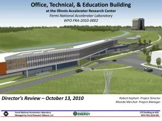
Location New Muon Lab 2007 FRA Visiting Committee – S. Nagaitsev
New Muon Lab building 2007 FRA Visiting Committee – S. Nagaitsev
NML inside (before) 2007 FRA Visiting Committee – S. Nagaitsev
NML inside (now) 2007 FRA Visiting Committee – S. Nagaitsev
Outline of our plans • Cryomodule delivery • 1st (Type 3+) cryomodule is planned to be delivered in fall, 2007 • 2nd (Type 3+) CM – summer 2008 • 3rd (ILC Type 4) CM – Mid FY09 • Replace all three CMs with ILC Type 4+ in FY2010 • The NML facility will start as a Cryomodule Test Stand in FY07-08 • FY08: add beam; start civil construction of the building extension • Convert to an ILC RF Unit beam test facility in FY11 2007 FRA Visiting Committee – S. Nagaitsev
NML Schedule (Phase-1) • Phase - 1 (FY07 thru early FY08) • Prepare Facility for Testing of Capture Cavity II (CCII) and 1st Cryomodule (CM1) without Beam • Building Infrastructure (AC Power, Water, Air, Mechanical) • Electrical Infrastructure (Racks, Trays, Cables) • Build Cave to Test these Devices (~ 3/4 of Full Cave) • RF Systems (3MW for CM and 300kW for CCII) • Cryogenic System (1st Refrigerator, Feed Can, Feed Cap, End Cap, Distribution) • Control Room • LLRF, Controls, Safety Systems, Instrumentation (non-beam) • Move CCII from Meson Detector Building (MDB) to NML • Cool-down and Power Testing 2007 FRA Visiting Committee – S. Nagaitsev
Phase 1: 1st CM (end of CY07) A used 3-MW Klystron, 10-MW, 1.5-ms modulator CC2 RF system Capture cavity 2 in its final location for the injector Type 3+ cryomodule 2007 FRA Visiting Committee – S. Nagaitsev
NML Schedule (Phase-2 & 3) • Phase - 2 (FY08) • Testing of 1st and 2nd Cryomodule without Beam, Prepare Facility for Beam • Receive, Install, Power, Cool-down 1st Cryomodule • Install New Gun and Relocate Injector to NML • Extend Cave • Install Beam Lines and Dumps • Install Additional RF Systems needed for CCI and Gun • Receive, Install, Power, Cool-down 2nd Cryomodule • Begin Building Extension needed for Phase-3 • Phase - 3 (FY09) • Testing of Full RF Unit with Beam • Complete Building Extension • Begin Testing with Beam • Install 3rd Cryomodule • Upgrade Cryomodule RF system to 10 MW 2007 FRA Visiting Committee – S. Nagaitsev
Two CMs with beam The existing building is perfect for testing two cryomodules with ILC-like beam. The building can be extended to fit 3 cryomodules. 2007 FRA Visiting Committee – S. Nagaitsev
ILC-like beam? • 3.2 nC/bunch @3 MHz, up to 3000 bunches @ 5Hz • Bunch length: 300-μm rms • Transverse emittance: not important (~5 μm) • Energy: 30-40 MeV (to avoid overfocusing in the CM operating at 31 MV/m) • Need “known and frozen” beam parameters at the cryomodule entrance 2007 FRA Visiting Committee – S. Nagaitsev
A0 Photoinjector 13m (CC-1) 2007 FRA Visiting Committee – S. Nagaitsev
Proposed NML Injector Layout 22m (CC-1, CC-2) (intended initially for ILC crab cavity tests) P. Piot 2007 FRA Visiting Committee – S. Nagaitsev
Building extension • Construct a new building ~50m away from NML. Connect by a tunnel when schedule allows. Move loading dock. • ILC-like tunnel, space for 3 more cryomodules • Room for a new cryo-plant 2007 FRA Visiting Committee – S. Nagaitsev
A list of some ILC tests at NML • Demonstrate stable long-term high-gradient beam operation at ILC-like bunch parameters. • Demonstrate HOM power absorption • While operating at high gradient and ILC-like beam currents, demonstrate a LLRF controls system such that the beam energy and beam phase stability meet the ILC specs. • Evaluate effects of cavity gradient spreads, dark current, cryogenic load, radiation levels with beam operation. • Measure beam kicks due to couplers, cavity tilt, quad rotations + tilt errors characterize focusing properties of SCRF cavities. • Measure vibrations of cavities and quads. • Test beam diagnostics. • Test ILC crab cavities. • Test the ILC installation procedure and tunnel layout. • May evolve into a near-final system integration test. 2007 FRA Visiting Committee – S. Nagaitsev
A facility to test ILC baseline and alternative designs • Many groups in the US and world-wide are looking for a place to test their ILC-related designs. • Need beam at 200-800 MeV, need space to set up tests • Baseline design: • “Keep alive” positron source (ANL) • SC undulator (Cornell) • Crab-cavity (SLAC, Cockcroft Inst) • Alternative designs: • New HOM coupler design (MIT) 2007 FRA Visiting Committee – S. Nagaitsev
AARD plans • The existence of the NML facility provides the opportunity to conduct an AARD program • Had a workshop in Nov 2006 • Fermilab wants to establish an AARD program at NML. • Flexible beam injector needed to support various beam parameters (emittance, bunch charge, bunch length) • Unique beam parameters anticipated: • Record high peak current of 14kA possible • ~30 um beam spot size (FWHM) • Beam energy up to 800 MeV • Structure: 3000 bunches or a witness bunch 300 um behind 2007 FRA Visiting Committee – S. Nagaitsev
AARD plans • Number of AARD experiments possible in NML itself: • one at low energy (50MeV), one-two at full energy (space!) • Building extension needed to provide area for 4-7 more Low energy test area 2007 FRA Visiting Committee – S. Nagaitsev
Collaborations DESY INFN SLAC ANL Rochester NIU Cockcroft KEK 2007 FRA Visiting Committee – S. Nagaitsev
Summary • Fermilab plans to create the NML facility to test the ILC RF unit (3 CMs) with beam at ILC-like parameters by FY10. • Planning and engineering designs underway • Building extension and new cryo plant are needed to meet demands of users (ILC, AARD). • Plans to use the NML for accelerator research and training; develop partnerships with NIU and other local universities. Collaborations with SLAC, KEK, DESY and ANL. • Building extension required to make it a users facility with competitive and flexible beam parameters. 2007 FRA Visiting Committee – S. Nagaitsev