Download
1 / 86
880 likes | 1.02k Views
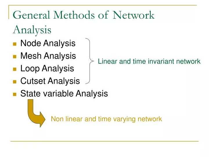
General Methods of Network Analysis. Node Analysis Mesh Analysis Loop Analysis Cutset Analysis State variable Analysis. Linear and time invariant network. Non linear and time varying network. Node and Mesh analyses. Source transformation Basic facts of node analysis Implication of KCL

E N D
General Methods of Network Analysis • Node Analysis • Mesh Analysis • Loop Analysis • Cutset Analysis • State variable Analysis Linear and time invariant network Non linear and time varying network
Node and Mesh analyses • Source transformation • Basic facts of node analysis • Implication of KCL • Implication of KVL • Node analysis of linear time invariant networks • Duality • Basic facts of mesh analysis • Implication of KVL • Implication of KCL • Mesh analysis of linear time invariant networks
Node and Mesh analyses Fig. 1
Source transformation Fig. 2 Ideal voltage source branch can be eliminated
Source transformation Fig. 3 Ideal current source branch can be eliminated
Source transformation summary • By source transformation we can modify any given network in such a way that each voltage source is connected in series with an element which is not a source and each current source is connected in parallel with an element which is not a source. • If a current source in connected in series with a voltage source or an element the voltage source or that element can be ignored in analyzing the circuit. • If a voltage source in connected in parallel with a current source or an element the current source or that element can be omitted in analyzing the circuit.
Basic facts of node analysis For any network with nodes and branches pick an arbitrary node called the datum node. Assign to all node as Where Implications of KCL Apply KCL to nodes a system of linear algebraic equation is obtained of unknowns obtained by “The n linear homogenous algebraic equations in applying KCL to each node except the datum node constitute a set of linearly independent equation.”
Basic facts of node analysis At node k Fig. 6 For all node KCL is written in the form (KCL) A is the reduced incident matrix. (Aa with datum node deleted)
Basic facts of node analysis Example 1 Consider the graph in Fig. 8. The graph has 4 nodes and 5 branches. Write The node incident matrix Aa and the KCL in matrix form. Fig. 8 Incident matrix Aa
Basic facts of node analysis KCL or
Basic facts of node analysis Implications of KVL Let be the node voltage at nodes respect to the datum node. The kth branch voltage is always the difference Between the nodes connected to it. Therefore all branch voltage can be written in the matrix form (KVL) if branch k leaves node i if branch k enters node i
Basic facts of node analysis If branch leaves node and enter node then In matrix form If branch leaves node If branch enters node If branch is not incident with node
Basic facts of node analysis Example 2 For the graph of example 1 or KVL
Basic facts of node analysis Proof of Tellegen theorem From KVL and from KCL
Node analysis of linear time invariant networks In linear time invariant network all element except the independent source are linear and time invariant. The combination of branch equations to KCL and KVL forms a general linear simultaneous equation for Resistive network In a resistive network the branch equation takes the form or In matrix form Fig. 9 (1)
Node analysis of linear time invariant networks is called the branch conductance matrix and it is a diagonal matrix The and are source vectors Substitute and pre-multiply by A in (1) yields (2) or (3)
Node analysis of linear time invariant networks Let be the node admittance matrix and be the node current source vector Then the node equation becomes (4) Once the node voltages are known the branch currents can be found from and (5)
Node analysis of linear time invariant networks Example 3 Consider the circuit in example 1 with elements shown in Fig.10, solve the circuit for the node voltages and branch currents by node analysis. Fig.10
Node analysis of linear time invariant networks 1) Write KCL 2) Write KVL
Node analysis of linear time invariant networks 3) Write branch equation in the form Branch 1 Branch 5 Thus
Node analysis of linear time invariant networks 4) Make the form
Node analysis of linear time invariant networks 5) and 6) The node equation is
Node analysis of linear time invariant networks 7) Solve for e 8) Solve for v
Node analysis of linear time invariant networks 9) Solve for j
Node analysis of linear time invariant networks Node equation by inspection can be written in scalar form The node equation (6)
Node analysis of linear time invariant networks where = sum of admittance at node = negative sum of admittance between the node and the node and = equivalent current source injected at node Redraw the circuit in example 3 By inspection
Node analysis of linear time invariant networks Sinusoidal steady state analysis In RLC circuit with sinusoid excitations, branch voltage and branch current are in the form of phasors and branch admittances are the function of frequency The branch equation take the form (7) (8) In the matrix form (9) and the node equation becomes
Node analysis of linear time invariant networks Example 4 Consider the circuit shown in Fig.11. The sinusoid current source of phasor is applied at node 1. The inductors are coupled as shown by its inductance matrix Write the node equation of the circuit. Fig. 11
Node analysis of linear time invariant networks Branch equations Inductor branch equations
Node analysis of linear time invariant networks Branch equation in matrix form
Node analysis of linear time invariant networks The node admittance matrix
Node analysis of linear time invariant networks The node equation is Solve for E and substitute in and
Node analysis of linear time invariant networks Integrodifferential form equations In general node analysis of a linear network lead to a set of integro- differential equation. The equation involves unknown functions , theirs derivatives and integrals. e.g. Example 5 The linear time-invariant network shown in Fig.12 has the reciprocal Inductance matrix
Node analysis of linear time invariant networks Fig. 12 KCL:
Node analysis of linear time invariant networks KVL: Branch equation
Node analysis of linear time invariant networks It is convenient to write and Therefore the branch equations are
Node analysis of linear time invariant networks In the matrix form Multiple by A and from KVL or
Node analysis of linear time invariant networks The node equation The cut set for branches1, 4, 5 gives initial conditions (a)
Node analysis of linear time invariant networks Notes If we define new variables Then The node equation becomes as in (a)
Node analysis of linear time invariant networks The short cut method If the circuit involves only few dependent sources the node equation can also be written by inspection. Example 6 Write the node equation for Fig. 13 in sinusoid steady state. Fig.13
Node analysis of linear time invariant networks By inspection consider as independent sources
Node analysis of linear time invariant networks Rearrange the equation
Node analysis of linear time invariant networks Example 7 Write the integro-differential equation by inspection for the circuit in Fig.14 Fig.14
Node analysis of linear time invariant networks Since Then by inspection substitute Then
Node analysis of linear time invariant networks A graph of a circuit can be drawn in many ways but it has the same results. • Duality • Planar graph, Meshes, outer mesh A planar graph can be drawn on the plane without branch intersection. A mesh is the smallest closed path (loop) in a graph and a outer mesh Is a loop formed outside the graph. Fig.15