Download
1 / 35
350 likes | 486 Views
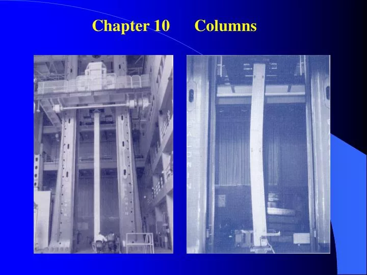
Chapter 10 Columns . 10.1 Introduction. Column = vertical prismatic members subjected to compressive forces. Goals of this chapter: Study the stability of elastic columns Determine the critical load P cr The effective length Secant formula. Previous chapters:

E N D
10.1 Introduction Column = vertical prismatic members subjected to compressive forces • Goals of this chapter: • Study the stability of elastic columns • Determine the critical load Pcr • The effective length • Secant formula
Previous chapters: -- concerning about (1) the strength and (2) excessive deformation (e.g. yielding) This chapter: -- concerning about (1) stability of the structure (e.g. bucking)
10.2 Stability of Structures Concerns before: Stable? Unstable? New concern: (10.1) (10.2)
Since (10.2) The system is stable, if The system is unstable if A new equilibrium state may be established
The new equilibrium position is: (10.3) or
After the load P is applied, there are three possibilities: 1. P < Pcr – equilibrium & = 0 -- stable 2. P > Pcr – equilibrium & = -- stable 3. P > Pcr – unstable – the structure collapses, = 90o
10.3 Euler’s Formula for Pin-Ended Columns Determination of Pcr for the configuration in Fig. 10.1 ceases to be stable Assume it is a beam subjected to bending moment: (10.4) (10.5)
Defining: (10.6) (10.7) The general solution to this harmonic function is: (10.8) B.C.s: @x = 0, y = 0 B = 0 @x = L, y = 0 Eq. (10.8) reduces to (10.9)
(10.9) Therefore, 1. A = 0 y = 0 the column is straight! 2. sin pL = 0 pL = n p = n /L (10.6) Since We have (10.10) For n = 1 -- Euler’s formula (10.11)
Substituting Eq. (10.11) into Eq. (10.6), (10.11) (10.6) Therefore, Hence Equation (10.8) becomes (10.12) This is the elastic curve after the beam is buckled.
(10.9) 1. A = 0 y = 0 the column is straight! 2. sin pL = 0 pL = n If P < Pcr sin pL 0 Hence, A = 0 and y = 0 straight configuration
Critical Stress: Introducing Where r = radius of gyration Where r = radius of gyration (10.13) L/r = Slenderness ratio
10.4 Extension of Euler’s Formula to columns with Other End Conditions Case A: One Fixed End, One Free End (10.11') (10.13') Le = 2L
Case B: Both Ends Fixed At Point C RCx = 0 Q = 0 Point D = inflection point M = 0 AD and DC are symmetric Hence, Le = L/2
Case C: One Fixed End, One Pinned End M = -Py - Vx Since Therefore, The general solution: The particular solution:
Substituting into the particular solution, it follows As a consequence, the complete solution is (10.16)
(10.16) B.C.s: @x = 0, y = 0 B = 0 @x = L, y = 0 (10.17) Eq. (10.16) now takes the new form
Taking derivative of the question, B.C.s: @ x = L, dy/dx = = 0 (10.18) (10.17) (10.19)
Solving Eq. (10.19) by trial and error, Since Therefore, Solving for Le Case C Le = 0.699L 0.7 L
Secant Formula: (10.36) If Le/r << 1, Eq. (10.36) reduces to (10.37)
10.6 Design of Columns under a Centric Load Assumptions in the preceding sections: -- A column is straight -- Load is applied at the center of the column -- < y Reality: may violate these assumptions -- use empirical equations and rely lab data
Test Data: Facts: 1. Long Columns: obey Euler’s Equation 2. Short Columns: dominated by y 3. Intermediate Columns: mixed behavior
Real Case Design using Empirical Equations: 1. Allowable Stress Design Two Approaches: 2. Load & Resistance Factor Design
Structural Steel – Allowable Stress Design Approach I -- w/o Considering F.S. 1. For L/r Cc [long columns]: [Euler’s eq.] 2. For L/r Cc [short & interm. columns]: where
Approach II -- Considering F.S. 1. L/r Cc : (10.43) 2. L/r Cc : (10.45)
10.7 Design of Columns under an Eccentric Load (10.56) 1. The section is far from the ends 2. < y (10.57) Two Approaches: (I) Allowable Stress Method (II) Interaction Method
I. Allowable-Stress Method (10.58) -- all is obtained from Section 10.6. -- The results may be too conservative.
II. Interaction Method Case A: If P is applied in a plane of symmetry: (10.59) (Interaction Formula) (10.60) -- determined using the largest Le