Download
1 / 38
410 likes | 556 Views
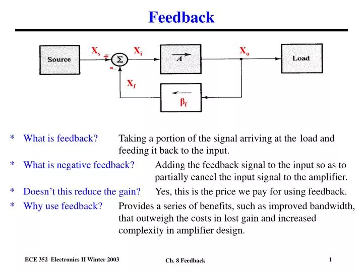
Feedback. What is feedback? Taking a portion of the signal arriving at the load and feeding it back to the input. What is negative feedback? Adding the feedback signal to the input so as to partially cancel the input signal to the amplifier.

E N D
Feedback • What is feedback? Taking a portion of the signal arriving at the load and feeding it back to the input. • What is negative feedback? Adding the feedback signal to the input so as to partially cancel the input signal to the amplifier. • Doesn’t this reduce the gain? Yes, this is the price we pay for using feedback. • Why use feedback? Provides a series of benefits, such as improved bandwidth, that outweigh the costs in lost gain and increased complexity in amplifier design. Xs Xi Xo + - Xf βf Ch. 8 Feedback
Feedback Amplifier Analysis Xs Xi Xo + - Xf βf Ch. 8 Feedback
Advantages of Negative Feedback • Gain desensitivity - less variation in amplifier gain with changes in (current gain) of transistors due to dc bias, temperature, fabrication process variations, etc. • Bandwidth extension - extends dominant high and low frequency poles to higher and lower frequencies, respectively. • Noise reduction - improves signal-to-noise ratio • Improves amplifier linearity - reduces distortion in signal due to gain variations due to transistors • Cost of these advantages: • Loss of gain, may require an added gain stage to compensate. • Added complexity in design Ch. 8 Feedback
Basic Types of Feedback Amplifiers • There are four types of feedback amplifiers. Why? • Outputsampled can be a current or a voltage • Quantity fed back to input can be a current or a voltage • Four possible combinations of the type of output sampling and input feedback • One particular type of amplifier, e.g. voltage amplifier, current amplifier, etc. is used for each one of the four types of feedback amplifiers. • Feedback factor f is a different type of quantity, e.g. voltage ratio, resistance, current ratio or conductance, for each feedback configuration. • Before analyzing the feedback amplifier’s performance, need to start by recognizing the type or configuration. • Terminology used to name types of feedback amplifier, e.g. Series-shunt • First term refers to nature of feedback connection at the input. • Second term refers to nature of sampling connection at the output. Ch. 8 Feedback
Basic Types of Feedback Amplifiers Series - Shunt Shunt - Series Series - Series Shunt - Shunt Ch. 8 Feedback
Method of Feedback Amplifier Analysis • Recognize the feedback amplifier’s configuration, e.g. Series-shunt • Calculate theappropriate gain A for the amplifier, e.g. voltage gain. • This includes the loading effects of the feedback circuit (some combination of resistors) on the amplifier input and output. • Calculate the feedback factorf • Calculate the factorfA and make sure that it is: 1) positive and 2) dimensionless • Calculate the feedback amplifier’s gain with feedback Afusing • Calculate the final gain of interest if different from the gain calculated, e.g. Current gain if voltage gain originally determined. • Determine the dominant low and high frequency poles for the original amplifier, but taking into account the loading effects of the feedback network. • Determine the final dominant low and high frequency poles of the amplifier with feedback using Ch. 8 Feedback
Series-Shunt Feedback Amplifier - Ideal Case • Assumes feedback circuit does not load down the basic amplifier A, i.e. doesn’t change its characteristics • Doesn’t change gain A • Doesn’t change pole frequencies of basic amplifier A • Doesn’t change Ri and Ro • For the feedback amplifier as a whole, feedback does change the midband voltage gain from A to Af • Does change input resistance from Ri to Rif • Does change output resistance from Ro to Rof • Does change low and high frequency 3dB frequencies Basic Amplifier Feedback Circuit Equivalent Circuit for Feedback Amplifier Ch. 8 Feedback
Series-Shunt Feedback Amplifier - Ideal Case Midband Gain Input Resistance Output Resistance It Vt Ch. 8 Feedback
Series-Shunt Feedback Amplifier - Ideal Case Low Frequency Pole Low 3dB frequency lowered by feedback. High Frequency Pole Upper 3dB frequency raised by feedback. Ch. 8 Feedback
Practical Feedback Networks • Feedback networks consist of a set of resistors • Simplest case (only case considered here) • In general, can include C’s and L’s (not considered here) • Transistors sometimes used (gives variable amount of feedback) (not considered here) • Feedback network needed to create Vf feedback signal at input (desirable) • Feedback network has parasitic (loading) effects including: • Feedback network loads down amplifier input • Adds a finite series resistance • Part of input signal Vs lost across this series resistance (undesirable), so Vi reduced • Feedback network loads down amplifier output • Adds a finite shunt resistance • Part of output current lost through this shunt resistance so not all output current delivered to load RL (undesirable) Vi Vo Vf • How do we take these • loading effects into account? Ch. 8 Feedback
Equivalent Network for Feedback Network • Need to find an equivalent network for the feedback network including feedback effect and loading effects. • Feedback network is a two port network (input and output ports) • Can represent with h-parameter network (This is the best for this particular feedback amplifier configuration) • h-parameter equivalent network has FOUR parameters • h-parameters relate input and output currents and voltages • Two parameters chosen as independent variables. For h-parameter network, these are input current I1 and output voltage V2 • Two equations relate other two quantities (output current I2 and input voltage V1) to these independent variables • Knowing I1 and V2, can calculate I2 and V1 if you know the h-parameter values • h-parameters can have units of ohms, 1/ohms or no units (depends on which parameter) Ch. 8 Feedback
Series-Shunt Feedback Amplifier - Practical Case • Feedback network consists of a set of resistors • These resistors have loading effects on the basic amplifier, i.e they change its characteristics, such as the gain • Can use h-parameter equivalent circuit for feedback network • Feedback factor f given by h12 since • Feedforward factor given by h21 (neglected) • h22 gives feedback network loading on output • h11 gives feedback network loading on input • Can incorporate loading effects in a modified basic amplifier. Basic gain of amplifier AV becomes a new, modified gain AV’ (incorporates loading effects). • Can then use feedback analysis from the ideal case. Ch. 8 Feedback
Series-Shunt Feedback Amplifier - Practical Case Summary of Feedback Network Analysis • How do we determine the h-parameters for the feedback network? • For the input loading term h11 • Turn off the feedback signal by setting Vo = 0. • Then evaluate the resistance seen looking into port 1 of the feedback network (also called R11 here). • For the output loading term h22 • Open circuit the connection to the input so I1 = 0. • Find the resistance seen looking into port 2 of the feedback network (also called R22 here). • To obtain the feedback factor f (also called h12 ) • Apply a test signal Vo’ to port 2 of the feedback network and evaluate the feedback voltage Vf (also called V1 here) for I1 = 0. • Find f from f = Vf/Vo’ Ch. 8 Feedback
Series-Shunt Feedback Amplifier - Practical CaseSummary ofApproach to Analysis • Evaluate modified basic amplifier (including loading effects of feedback network) • Including h11 at input • Including h22 at output • Including loading effects of source resistance • Including load effects of load resistance • Analyze effects of idealized feedback networkusingfeedback amplifier equations derived • Note • Av’ is the modified voltage gain including the effects of h11 , h22 , RS and RL. • Ri’, Ro’ are the modified input and output resistances including the effects of h11 , h22 , RS and RL. Basic Amplifier Practical Feedback Network Modified Basic Amplifier Idealized Feedback Network Ch. 8 Feedback
Example - Series-Shunt Feedback Amplifier • Two stage amplifier • Each stage a CE amplifier • Transistor parameters Given: 1= 2 =50, rx1=rx2=0 • Coupled by capacitors, dc biased separately • DC analysis: DC analysis for each stage can be done separately since stages are isolated (dc wise) by coupling capacitors. Ch. 8 Feedback
Example - Series-Shunt Feedback Amplifier • Redraw circuit to show • Feedback circuit • Type of output sampling (voltage in this case = Vo) • Type of feedback signal to input (voltage in this case = Vf) + _ Vi + + Vo Vf _ _ Ch. 8 Feedback
Example - Series-Shunt Feedback Amplifier Input Loading Effects Vo=0 Output Loading Effects I1=0 Amplifier with Loading Effects R2 R1 Ch. 8 Feedback
Example - Series-Shunt Feedback Amplifier • Construct ac equivalent circuit at midband frequencies including loading effects of feedback network. • Analyze circuit to find midband gain (voltage gain for this series-shunt configuration) R1 R2 R2 R1 Ch. 8 Feedback
Example - Series-Shunt Feedback Amplifier Midband Gain Analysis Ch. 8 Feedback
Midband Gain with Feedback • Determine the feedback factor f • Calculate gain with feedback Avf • Note • f Avo > 0 as necessary for negative feedback • f Avo is large so there is significant feedback. For f Avo 0, there is almost no feedback. • Can change f and the amount of feedback by changing Rf1 and/or Rf2. • NOTE: Since f Avo >> 0 Ch. 8 Feedback
Input and Output Resistances with Feedback • Determine input Ri and output Ro resistances with loading effects of feedback network. • Calculate input Rif and output Rof resistances for the complete feedback amplifier. Ch. 8 Feedback
Equivalent Circuit for Series-Shunt Feedback Amplifier • Voltage gain amplifier • Modified voltage gain, input and output resistances • Included loading effects of feedback network • Included feedback effects of feedback network • Include source resistance effects • Significant feedback, i.e. f Avo is large and positive Ch. 8 Feedback
Low Frequency Poles and Zeros for Series-Shunt Feedback Amplifier • Six capacitors: • Input and output coupling capacitors C1 and C5 • Emitter bypass capacitors C3 and C4 • Interstage coupling capacitors C2 • Feedback coupling capacitor C6 • Analyze using Gray-Searle (Short Circuit) Technique one capacitor at a time • Find dominant low frequency pole (highest frequency one) Ch. 8 Feedback
Example - Input Coupling Capacitor’s Pole Frequency Equivalent circuit for C1 Note that there are some loading effects of the feedback network on this pole frequency. In Ri1 the feedback resistors determine R1 Ch. 8 Feedback
Example - Interstage Coupling Capacitor’s Pole Frequency Equivalent circuit for C2 Note: No RE2 since C4 shorts it out. Ch. 8 Feedback
Example - Feedback Coupling Capacitor’s Pole Frequency Equivalent circuit for C6 Ch. 8 Feedback
Example - Emitter Bypass Capacitor’s Pole Frequency Equivalent circuit for C3 IE1 Ch. 8 Feedback
Example - Emitter Bypass Capacitor’s Pole Frequency Equivalent circuit for C4 IE2 Ch. 8 Feedback
Example - Output Coupling Capacitor’s Pole Frequency Equivalent circuit for C5 Ch. 8 Feedback
Zeros for Series-Shunt Feedback Amplifier Example • Coupling capacitors C1, C2 and C5 give zeros at = 0 since ZC = 1/sC and they are in the signal line. • Emitter bypass capacitors C3 and C4 give a zero when the impedance ZCE ||RE. • Feedback capacitor C6 gives a zero when [ZC6 +R2]||RC2 when Ch. 8 Feedback
Series-Shunt Example - Low Frequency • Midband Gain Low Frequency Poles Low Frequency Zeros Low 3dB Frequency Ch. 8 Feedback
Series-Shunt Example - High Frequency • Substitute hybrid-pi model for transistor with C and C • Short all coupling capacitors and emitter bypass capacitors • Include loading effects of feedback network R1 and R2 • Find high frequency poles and zeros using Gray-Searle (Open Circuit) Method Ch. 8 Feedback
Series-Shunt Example - High Frequency Pole - C1 Given: C1 = 15 pF IS I1 Ch. 8 Feedback
Series-Shunt Example - High Frequency Pole - C1 Given: C1 = 1.2 pF Ch. 8 Feedback
Series-Shunt Example - High Frequency Pole - C2 Given: C2 = 12 pF Ch. 8 Feedback
Series-Shunt Example - High Frequency Pole - C2 Given: C2 = 1.4 pF Ch. 8 Feedback
Series-Shunt Example - High Frequency Zeros - C1 &C2 I2 For CE amplifier, a high frequency zero occurs when ZH = gm/C Ch. 8 Feedback
Series-Shunt Example - High Frequency • Midband Gain High Frequency Poles High Frequency Zeros High 3dB Frequency Ch. 8 Feedback