Download
1 / 20
240 likes | 871 Views
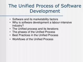
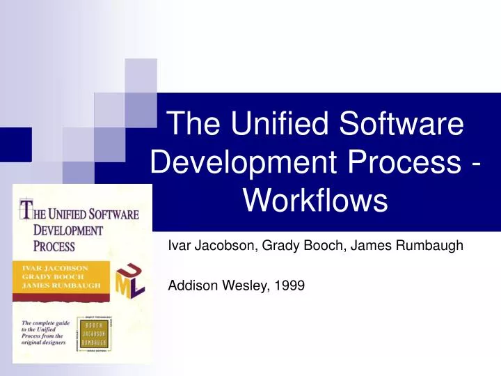
The Unified Software Development Process - Workflows. Ivar Jacobson, Grady Booch, James Rumbaugh Addison Wesley, 1999. Remainder. p. 11. Workflows. The Workflows are carried in each iteration as far as required for a particular iteration.

E N D
The Unified Software Development Process -Workflows Ivar Jacobson, Grady Booch, James Rumbaugh Addison Wesley, 1999
Remainder p. 11
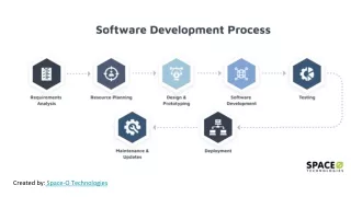
Workflows • The Workflows are carried in each iteration as far as required for a particular iteration. • Workflows interact byusing one another’s products and widening them. • Traceability - one can trace back and forward the products of each workflow. • Workflows can be alternate forth and back during iteration.
UML – Unified Modeling Language • Standard modeling language for software. • “Language for visualizing, specifying, constructing, and documenting the artifacts of a software intensive system” • Goes hand by hand with the Unified Software Development Process. • The artifacts and products of each workflow are written by UML. • I will explain the idea behind the artifacts, I will not show the artifacts representation in UML.
Requirements Capture • Requirements capture – the process of finding out, usually under difficult circumstances, what is to be built. • Why requirements capture is difficult? • Developers of the system are usually not the users. • The users don’t know what are the requirements or how to specify them in a precise manner. • Systems are big and has many users and users types – no one can see the whole picture. • Each system has it own unique requirements and functionalities.
Requirements workflow • Purpose – building the right system. • Achieved by: • Describing the requirements well enough so that an agreement can be reached between customer and developers on what system should and should not do. • Use the customer language to describe the results of the requirements capture.
Requirements Workflow Main Products • Actors – each type of user and each external system interacts with are represented as actors • Use Cases – each way the actors use the system is represented as a use case. “Chunks” of functionality that of the system. • Special requirements – non-functionality requirements which has to be dealt in a use case – written in the appropriate use case as text. • Use-Case model – holds all of the use cases, actors and their relations. • Architecture Description – the important use cases of the model. Used for prioritizing developing of uses cases.
Analysis • Since we focused on the customer language - requirements workflow leave some unresolved issues in the system description: internal details, interfaces, redundancies etc. • Analyzing the requirements mode in-depth and supply more formally results. The results given in the developer language. • Give more precise specification of the system.
Analysis Main Products • Analysis class –Conceptual, functional, high level representation of one or several classes and/or subsystems in the system. • Use-Case realization - Analysis – description of how a specific use case is realized and performed in terms of analysis classes and their interacting analysis objects. Contains: • Class diagram – the classes that participate in the use-case realization. • Interaction diagram – describe the sequence of actions in a use case in general i.e. which class is applying which class and when in the realization.
Analysis Main Products – Cont. • Analysis classes and Use-Case realization can be organized on analysis packages. • Analysis model - contains the analysis classes, use-case realizations and packages. • Architecture description – contain architectural view of the analysis model – description of the components in the Analysis model which consider to be crucial for the system architecture. (main use-case realizations, key analysis classes etc.).
Design • Shaping the system and its form that lives up to all requirements. • Acquire in-depth understanding of non-functional requirements and other constrains like: programming languages, OS, DB technologies, UI technologies etc. • Capturing requirements for on individual subsystems, interfaces and classes. • Capture major interfaces between subsystems early as possible in software life’s cycle.
Design – Cont. • Decompose the implementation (on next workflow) into manageable and independent tasks. • Create seamless abstraction of the system’s implementation so the implementation will be straightforward refinement of the design by filling in the “meat” but not changing the structure.
Design Main Products • Design Class – seamless abstraction of class in the system’s implementation including: • Attributes and their visibility • Methods • Etc. • Use-Case realization - Design – specification of how specific use case is realized and performed in terms of design classes. Contain: • Class diagram – the classes that participates the realization of the use case and their relationships. • Interaction diagram - describe the sequence of actions in a use case which method of which class is called by which class etc.
Design Main Products – Cont. • Interface – specify the operations provides by design classes and subsystems. • Classes and use case realizations can be organized in Design subsystems. • Design model – all design classes, use-case realizations and subsystems. • Architecture description (view of design model) – contain architectural view of the design model – description of the components in the design model which consider to be crucial for the system architecture. (e.g. design subsystems and their interfaces and dependencies, key design classes, key use-case realizations).
Implementation • Implement the system in terms of components that is source code, scripts, binaries etc. • Implement the design classes and subsystems. • Unit test the components of the implementation.
Implementation Main Products • Source code files, executables, binaries, libraries, etc. All these actual files which product by an implementation are called Build. • Also UML objects: Component – represents an actual product of the implementation. • Interface – describe the operations which implemented by components or implementation subsystem.
Implementation Main Products – Cont. • Implementation subsystem – organize some components and their interfaces. • Implementation model – contain all components, interfaces and implementation subsystems. • Architecture description (implementation view) – contain architectural view of the implementation view model – description of the components in the implementation model which consider to be crucial for the system architecture. (e.g. Key components, main subsystem and their interfaces).
Test • Verify the result from implementation be testing each build. • Integration tests. • Plan the required test in each iteration. • Design and implement tests by creating test cases. • Perform the test cases and handle the tests results: • If a test of a build fails then it is retested and might sent back to previous workflows in order to fix significant defects.
Test Products • Test case – specifies one way to test the system. Includes: • What to test – generally one use-case (“black box”) or use-case realization-design (“white box”) or a specific scenario of a use case or use case realization-design. • Input, test conditions. • Expected result • Test procedure – specify how to perform a test case, a series of test case or a part of test case. • Test component (drivers) – automation of one or several test cases. Used to tests the components of the implementation workflow.
Test Products – Cont. • Test Plan – the strategies, resources and schedules of the testing. • Defect – bug or other problem which was found during the tests. • Test Evaluation – the state of the testing process and the current defects status.