Download

1 / 36
390 likes | 1.13k Views
Fiber-Optic Communication Systems An Introduction. Xavier Fernando Ryerson University. Why Optical Communications?. Optical Fiber is the backbone of the modern communication networks The Optical Fiber Carries: Almost all long distance phone calls

E N D
Fiber-Optic Communication Systems An Introduction Xavier Fernando Ryerson University
Why Optical Communications? • Optical Fiber is the backbone of the modern communication networks • The Optical Fiber Carries: • Almost all long distance phone calls • Most Internet traffic (Dial-up, DSL or Cable) • Most Television channels (Cable or DSL) • Most LAN, WAN and much more • One fiber can carry up to 6.4 Tb/s (1012 b/s) or 100 million conversations simultaneously
Why Optical Communications? Lowest Attenuation: 0.2 dB/km at 1.55 µm band resulting in 100s of km links without repeaters (very useful in under-see communication) Highest Bandwidth of any communication channel: Single Mode Fiber (SMF) offers the lowest dispersion highest bit rate rich content (broadband multimedia) Upgradability: Via Wavelength Division Multiplexing (WDM) Low Cost: Fiber is made of Silica (earth), much low cost than copper
Why OPTICOMfor you? • Most of you will eventually work in Information and Communications Technology (ICT) area • 138,000 ICT engineers hired in US in 2006 compared to 14000 in biomedical • (http://www.bls.gov/oco/ocos027.htm) • Canada produces 40% of the worlds optoelectronic products (Nortel, JDS Uniphase, Quebec Photonic Cluster…)
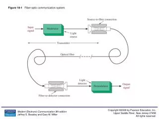
Elements of OPTICOM System • The Fiber – that carries the light • Single Mode Fiber (only one EM mode exists), offers the highest bit rate, most widely used • Multi Mode Fiber (multiple EM modes exist), hence higher dispersion (due to multiple modes) cheaper than SMF, used in local area networks • Step Index Fiber – two distinct refractive indices • Graded Index Fiber – gradual change in refractive index
Elements of OPTICOM System • Optical Transmitter converts the electrical information to optical format (E/O) • Light Emitting Diode (LED): cheap, robust and used with MMF in short range applications • Surface emitting and edge emitting LED • LASER Diode: high performance and more power, used with SMF in high speed links • Distributed Feedback (DFB) Laser – high performance single mode laser • Fabry-Perrot (FP) lasers – low performance multimode laser
Elements of OPTICOM System • Optical Receiver convertsthe optical signal into appropriate electrical format (E/O) • PIN Photo Diode: Low performance, no internal gain, low cost, widely used • Avalanche Photo Diode (APD): High performance with internal (avalanche) gain • Repeater: receives weak light signal, cleans-up, amplifies and retransmits (O/E/O) • Optical Amplifier: Amplifies light in fiber without O/E/O
Wavelength Division Multiplexing • Fiber has the capability to transmit hundreds of wavelengths • Cost effective only in long haul links in the past • With low cost Coarse WDM (CWDM) equipment this is possible even in the access front • Once the fiber is in place, additional wavelength can be launched at both ends by replacing transceivers
Optical Amplifier & EDFA • An optical amplifier amplifies the light signal without converting to electrical • Very useful is WDM systems • Erbium Doped Fiber Amplifier (EDFA) works in 1550 nm band Continuous Wave (Constant)
Long Haul Network Basics of Communication Networks
Brief History of Networks Copper Telecom Networks: • 4 kHz analog voice local loop (between customers and central office – access end) still in Bell Telephone lines & 56k modems • Digital interoffice trunks using DS-1 (Digital Signal Type 1) • A voice signal digitized at a sampling rate of 8 kHz 8 bits/samples is DS-0 (64 kb/s) • Carried on a single twisted copper-wire pair • Required repeaters every 2 km to compensate for attenuation
Digital Transmission Hierarchy (DTH) 64-kb/s circuits are multiplexed into higher-bit-rate formats Called Telephony or T-Networks This is Copper network
First Generation Fiber Optic Systems Purpose: • Eliminate repeaters in T-1 systems used in inter-office trunk lines Technology: • 0.8 µm GaAs semiconductor lasers • Multimode silica fibers Limitations: • Fiber attenuation • Intermodal dispersion Deployed since 1974
Second Generation Systems Opportunity: • Development of low-attenuation fiber (removal of H2O and other impurities) • Eliminate repeaters in long-distance lines Technology: • 1.3 µm multi-mode semiconductor lasers • Single-mode, low-attenuation silica fibers • DS-3 signal: 28 multiplexed DS-1 signals carried at 44.736 Mbits/s Limitation: • Fiber attenuation (repeater spacing ≈ 6 km) Deployed since 1978
Third Generation Systems Opportunity: • Deregulation of long-distance market Technology: • 1.55 µm single-mode semiconductor lasers • Single-mode, low-attenuation silica fibers • OC-48 signal: 810 multiplexed 64-kb/s voice channels carried at 2.488 Gbits/s Limitations: • Fiber attenuation (repeater spacing ≈ 40 km) • Fiber dispersion Deployed since 1982
Fourth Generation Systems Opportunity: • Development of erbium-doped fiber amplifiers (EDFA) Technology (deployment began in 1994): • 1.55 µm single-mode, narrow-band semiconductor lasers • Single-mode, low-attenuation, dispersion-shifted silica fibers • Wavelength-division multiplexing of 2.5 Gb/s or 10 Gb/s signals Nonlinear effects limit the following system parameters: • Signal launch power • Propagation distance without regeneration/re-clocking • WDM channel separation • Maximum number of WDM channels per fiber Polarization-mode dispersion limits the following parameters: • Propagation distance without regeneration/re-clocking
Fiber Network Topologies Core - Combination of switching centers and transmission systems connecting switching centers. Access- that part of the network which connects subscribers to their immediate service providers LWPF : Low-Water-Peak Fiber, DCF : Dispersion Compensating Fiber, EML : Externally modulated (DFB) laser
Synchronous Optical Networks • SONET is the TDM optical network standard for North America (called SDH in the rest of the world) • We focus on the physical layer • STS-1, Synchronous Transport Signal consists of 810 bytes over 125 us • 27 bytes carry overhead information • Remaining 783 bytes: Synchronous Payload Envelope
Last Mile Bottle Neck and Access Networks Infinite Bandwidth Backbone Optical Fiber Networks A few (Gb/s) Virtually infinite demand end user Few Mb/s The Last Mile ? ? Additionally, supporting different QoS
Fiber in the Access End Passive Optical Networks (PON) – No active elements or O/E conversion Fibre-Coaxial (analog) or DSL (digital) fibre-copper systems Radio over fibre (Fibre-Wireless) Systems Currently Drives the Market
Analog Systems: Sub Carrier Multiplexing (SCM) • Several RF carriers are frequency division multiplexed over single fiber • Each RF Carrier is an independent communication channel • Ex: CATV System
Digital Subscriber Loop • DSL consists of fiber-twisted pair • This is a digital fiber-copper link • Multimedia (video and data) supported over voice • At least 3.7 Mb/s streaming is needed for quality video • Bit rate heavily depend on the length of the twisted pair link • New techniques like very high rate DSL (VDSL) are tried • Some new condominiums in Toronto have access to video over DSL
PON Flavours • APON/BPON: ATM/Broadband PON • Uses ATM as bearer protocol • 155 or 622 Mbps downstream, 155 upstream. • EPON: Ethernet PON • Uses Ethernet framesfor data transfer • 10G-EPON aims at reaching high data rates of 10 Gb/s • GPON: Gigabit capable PON - successor of BPON • Enables the transmission of both ATM cells and Ethernet packets in the same transmission frame structure. • WPON: WDM-PON • Support multiple wavelengths
Radio over Fiber • ROF is the most promising emerging area for fiber optics • Fiber Ample bandwidth but no mobility • Wireless Mobility and flexibility but limited bandwidth (with long wireless link) • ROF systems integrates both advantages to provide Truly Broadband Mobility
Radio over Fiber (ROF) • RF signals are transmitted over fiber to the antennas that are closer to the user Shorter wireless channel Less fading and shadowing Low multipath spreading Low cost access points Rapid installation Good for hidden areas (tunnels mines etc)
ROF for Fiber-Wireless Networks Central Base Station RAP RAP RAP Y Radio over Fiber (ROF) (Simple) Up/Down links Y 802.11 voice Y Single ROF link can support voice and data simultaneously Micro Cell