Download
1 / 15
170 likes | 330 Views
SOAR Primary Mirror Active Tangent Link Design. Douglas R. Neill 8 / 19 / 05. Introduction.

E N D
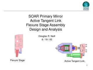
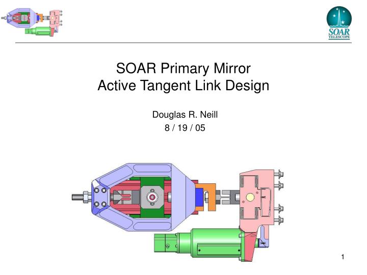
SOAR Primary Mirror Active Tangent Link Design Douglas R. Neill 8 / 19 / 05
Introduction • It has been determined, in several earlier studies, that the principle source of WFE, for the SOAR telescope, is primary mirror deformations produced by improper load distribution in the primary mirror tangent links. • To properly distribute the load in the tangent links, the present passive tangent links will be replaced with active tangent links. These tangent links will use electrical actuators to control the load in each active tangent link. • The purpose of this document is to present the current design of the proposed SOAR active tangent link assembly. Present Passive Tangent Link Proposed Active Tangent Link
Active Tangent Link Assembly Link End - Structure Load Cell Bolt Jam Nut Clevis Pin Assembly Bypass Link Load Cell Omega S Beam LCCA 10K Flexure Stage Anchor Bolts w Flat and Lock Washers Bypass Link Clamping Bolts Length Adjuster Bolt Link End - Mirror Linear Actuator Harmonic Drive Systems Inc. LAH-80 Flexure Mount Actuator Flexure Block
Minimum Factors of Safety • Stress factors of safety as defined by: • SF = expected failure stress / predicted stress. • Buckling factors of safety as defined by: • SF = expected buckling load / predicted load. • Minimum design factors of safety are the design requirements relative to maximum expected operational load of 2080 lbs combined with the maximum displacement of +/-1mm: • SF operate = 1.5 • SF yield = 2.5 • SF ultimate = 4.0 • SF buckling = 4.0 • Note: The majority of the stress in the flexure stage is the result of flexure bending and not the 2080 lbs expected maximum load. If the factors of safety is defined as expected failure load / predicted load, the resulting factors of safety would be much higher.
Top Level Requirements • The rated load cell accuracy is less than the required accuracy, however, the rating is the absolute accuracy while the requirement is the relative accuracy. The relative accuracy is the variation in measurement between load cells for a specific load. The expected value is ~ 1.0 lb. The measurement of the relative accuracy is planned. • The stiffness deficit will produce a small but tolerable increase in wind shake. • The actuator has not been tested by the manufacturer over the application temperature and altitude range. Testing is planned.
Actuator Harmonic Drive Systems Inc. LAH-80 • Step Size = 80nm, a factor of ~10 better than we need to resolve 1Kgf • Range = 50mm • Max Speed = 1.6mm/sec @ 20Khz, a factor of ~100 times more than we need • Max Force = 300Kgf (660 Lb) • Weight = 5Kg • Repeatability = 1um • Lost Motion = 10um • Stiffness = 40E6N/m (2.30e5 Lb/in) • Price = $5320 • Delivery = 8wks
Link Ends • The flexure design and the telescope interfaces of the original passive link ends will be retained. Re-engineering will not be necessary. New Active Designs Link End - Mirror Link End - Cell Original Passive Designs
Flexure Stage Assembly Material: CRES 440C 8x Translation Flexures 4x Flexure Shields 2x Travel Limits Flexure Mount Actuator Flexure Actuator Flexure Block 2x Lever Flexures Embedded Lever 4x 1/4 -28 SHCS
Flexure Dimensions Length: 0.335 in Width: 3.8 in Thickness: 0.025 in 16 Places Length: 0.585 in Width: 3.8 in Thickness: 0.080 in 8 Places Length: 0.50 in Width: 1.2 in (2x6in) Thickness: 0.030 in 1 Place Length: 0.50 in Width: 3.8 in Thickness: 0.040 in 2 Places
Load Cell • High Accuracy “S” Beam Load Cell • Environmentally protected. • Corrosion Resistant • Specifications: • Accuracy: 0.037% FS • Linearity: 0.03% FS • Repeatability: 0.01% FS • Hysteresis: 0.02% FS • Temp: 0 - 150 F • Stiffness: 5.88e5 lb/in • Mass: 3.5 lb • Load Capacity: • Operational: 10,000 lbs • Safe: 15,000 lbs • Ultimate: 30,000 lbs 4.25” 3.0” 1.25” ¾ x 16
Bypass Link • The maximum expected operating load of 2080 lbs produces a maximum stress of 7051 psi. • K = 1.35e6 lb/in Material: CRES 303 Weight: 9.0 Lb 1.8” 2.0” 11.3” 7.4”
0.5” 2.5” 1.125” Internal Thread Right Handed 3/4”- 16 Fine External Thread Right Handed 1”- 20 Extra Fine Length Adjuster Bolt • Course Resolution (360 degree): 0.0625 in • Fine Resolution (10 degree): 0.00035 in • Stroke: 0.40 in Material: CRES 416
Length Adjuster Bolt • Course length adjustment is accomplished by rotating the link end – mirror in 360 degree increments relative to stationary length adjuster bolt and bypass link. • Fine length adjustment is accomplished by holding the link end – mirror and the bypass link stationary and rotating the length adjuster bolt. 360 Degree Incremental Rotation Link End - Mirror Stationary: Bypass Link Link End - Mirror 10 Degree Incremental Rotation Length Adjuster Bolt Stationary: Bypass Link Length Adjuster Bolt
Gusset To Be Removed • The gusset to be removed is located directly below the Tangent Link to Primary Mirror Cell mounting location. Gusset to be Removed After Removal Before Removal