Download
1 / 15
150 likes | 287 Views
A NMR pulse is often designed to detect a certain outcome (state) but often unwanted states are present. Thus, we need to device ways to select desired outcome (Coherence transfer pathway) . Two ways to resolve the problem:

E N D
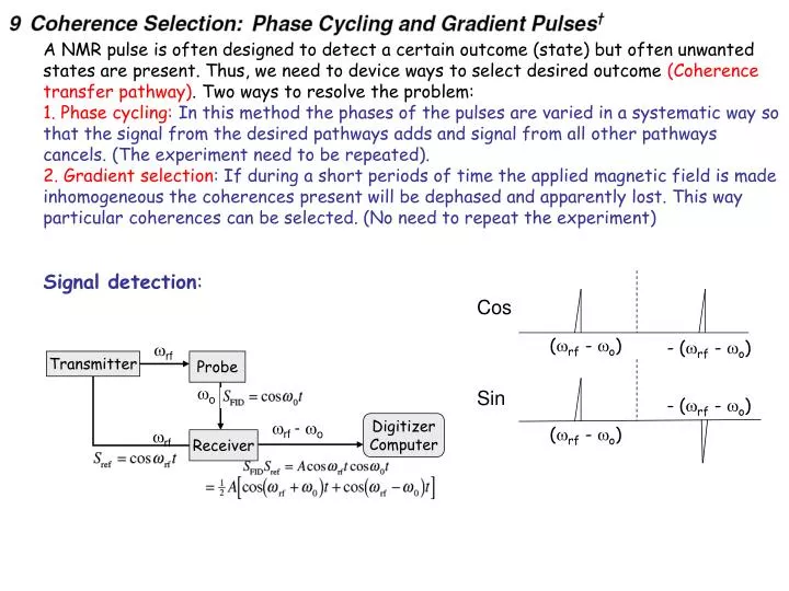
A NMR pulse is often designed to detect a certain outcome (state) but often unwanted states are present. Thus, we need to device ways to select desired outcome (Coherence transfer pathway). Two ways to resolve the problem: 1. Phase cycling: In this method the phases of the pulses are varied in a systematic way so that the signal from the desired pathways adds and signal from all other pathways cancels. (The experiment need to be repeated). 2. Gradient selection: If during a short periods of time the applied magnetic field is made inhomogeneous the coherences present will be dephased and apparently lost. This way particular coherences can be selected. (No need to repeat the experiment) Signal detection: Cos (rf - o) - (rf - o) rf Transmitter Probe o Sin - (rf - o) rf - o Digitizer Computer (rf - o) rf Receiver
Quadrature detection: Split the signal into two channels and mix one channel with cost and another channel with cos(t+/2) = sint and then combine the two channels into a complex signal for frequency discrimination Cos + iSin (rf - o)
Signal: In complex space (Phase sensitive detection): With T2 relaxation: Amplitude Frequency Decay rate 1/2 = 1/T2 Determined by
Lineshape and Frequency Discrimination NMR signal: = Lorentzian Absorption (A) Dispersion (D)
: If the pulse is applied in X-direction, instead of Y-direction then the dispersive and absorption signals will interchange their channels.
The phase of the signal is relative and is measured between the signal and the receiver. One can adjust the hardware (receiver or transmitter phase) or software to vary the phase of the phase of the resonance. Phase cycling:The hardware is usually imperfect. One best method to cancel the imperfection is to cycle through all phases and add them together. This is theCYCLOPscheme. In this scheme the pulse is phase cycled thru x,y,-x,-y, i.e. advance 90o in each step. The signal is added up after phase shifted accordingly. 90x 180x EXOCYCLOP Advance the 180o by 90o one must advance the receiver by 180o, i.e. pule (x,y,-x,-y) receiver (y,-y,y,-y). This will cancel out the imperfection in 180o pulse.
(b spectrum) If only the sine component is recorded, i.e. then: (c spectrum) Both spectra b and c are said to lack frequency discrimination, differ from a. O needs both sine and cosine components to have frequency discrimination
Phase modulation: Amplitude modulation No frequency discrimination Phase alteration of the pulses to generate since and cosine modulation and combine them into a phase sensitive mode (Phase sensitive detection). Phase Modulation: In general, the 2D spectrum will have the following form:
(+1, +2) (- 1, +2) Two phase-twisted lines: If we discard the imaginary part after the first Fourier transform we got: (No dispersive mode D)
:Similar results will be obtained if we start with the sine modulated signal (+1, +2) (- 1, +2) But opposite signs Two phase-twisted lines: If we discard the imaginary part after 1st FT we can again obtain pure absorptive signal Combine the pure absorption mode cosine and sine modulated signal we got: One absorption line at (+1, +2) In practice: The real part contains only one absorptive resonance at (1, 2)