Download
1 / 21
210 likes | 293 Views
International Workshop INFLUENCE OF ATOMIC DISPLACEMENT RATE ON RADIATION-INDUCED AGEING OF POWER REACTOR COMPONENTS: EXPERIMENTAL AND MODELING Ulyanovsk State U niversity, Russia, 3 – 7 October 2005.

E N D
International WorkshopINFLUENCE OF ATOMIC DISPLACEMENT RATE ONRADIATION-INDUCED AGEING OF POWER REACTOR COMPONENTS: EXPERIMENTAL AND MODELINGUlyanovsk State University, Russia, 3 – 7 October 2005 MAIN PROGRAMS AND TECHNIQUES FOR EXAMINATION OF BEHAVIOUR OF THE WWER HIGH-BURNUP FUEL IN THE MIR REACTOR А.V. Burukin, S.А. Ilyenko, V.А. Ovchinikov, V.N. Shulimov FSUE «SSC RIAR», Russia
2 Programs and techniques for in-pile examination of the WWER fuel are aimed at obtaining of experimental data to validate serviceability of the WWER fuel taking account of the following up-to-date trends: • Increase of burn-up and extension of the reactor cycle; • Introduction of maneuvering conditions; • Observance of the up-to-date requirements established for fuel behaviour under design-basis accidental conditions («Small LOCA», maximum design-basis accident, RIA)
3 Performance of the WWER standard fuel undernormal, transient and accidental operating conditions is simulated by conducting different tests including repeated irradiation and transient tests of full-size (FSFR) and refabricated (RFR) fuel rods as well as tests of the refabricated fuel rods under design-basis accidental (LOCA and RIA type) conditions and also tests of defective fuel rods. A highneutronfluxdensity andheat removal conditions allow the performance ofexperiments with fuel having a burnup of ~ 50...80 MWd/kgU at a linear power (LP) of ~ 50…100 kW/m.
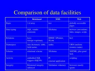
4 The MIR reactor is a channel-type, pool-type and beryllium-moderated reactor. It has several high-temperature loop facilities, which provide necessary coolant parameters for WWER fuel testing. Comparison of the main fuel testing conditions of the MIR loop facilities with operating conditions of the WWER-1000 fuel rods *- 4…5 g/kg - average level of index for WWER water-chemical conditionsfor long-term testing
5 Lay-out of the WWER experimental fuel rods in irradiation rigs
6 Types and characteristics of gauges for irradiation rigs and fuel rods * - experimental data for high-burnup fuel rods
7 Repeated irradiation of refabricated and full-size fuel rods Testing under design-basis RIA conditions Power ramping (RAMP) and stepwise increase of power (FGR) Tests of the WWER high-burnup fuel rodsin the MIR reactor Testing under power cycling conditions Testing under fuel rod drying, overheating and flooding conditions (LOCA) Testing of defective fuel rods
8 Repeated irradiation of refabricated and full-size fuel rods from spentWWER fuel assembliesup to high-burnup values The test objective is to determine the change of fuel rod state under burnup increase conditions at a specified power level and to prepare fuel rods with increased burnup for special tests (RAMP, LОСА and RIА). General data on repeated irradiation tests of the WWER fuel rods in the MIR reactor
9 Testing under power ramping conditions The tests aimed at determination of the effect of power ramping parameters (RAMP) (including FGR) on serviceability of fuel rods with different burnup. General information about FGR tests with the WWER fuel rods in the MIR reactor
10 Range of burnup and LP amplitudes in the course of RAMP tests of the WWER fuel rods in the MIR reactor
11 Testing under power cycling conditions (CMP-1, CYCLE 1, CYCLE 2) The objective of testing was to obtain experimental data that characterize a change in the cladding strain, gas pressure in the free volume of a fuel rod, fuel temperature in course of power changing and fuel rod state after testing. The main data of the CMP-1 test
12 General information about the CYCLE-1 and CYCLE-2 tests *- maximum values of initial LP, increment and power increase rate under ramping conditions after maneuvering
13 Testing of defective fuel rods with high-burnup The main examination tasks are as follows: • Formation of parametric dependences of fission product release (different physical-chemical groups and separate nuclides) on fuel burnup, power level, type and size of the cladding and location of the cladding defect; • Definition of kinetics and features of the cladding defect evolution including generation of the secondary defect Types of experimental data obtained during examination of fission product release into coolant
14 Cross-section of irradiation rig for testing defective fuel rod Lay-out of the special equipment for determination of fission product releaseintothe coolant of the loop facility primary circuit in the MIR reactor
15 Testing under fuel rod drying, overheating and flooding conditions (LOCA) The objective of the tests is to verify or refine serviceability criteria of fuel rodsand fuel assemblies, determine ultimate parameters, which allow the coredisassembling after operation under deteriorated heat transfer conditions, and toobtain data for code verification and improvement. Testing of the WWER fuel assembly fragments under «Small LOCA»conditions was performed in accordance with a special program that provideda widerange of environmental conditions.
16 The WWER-1000 fuel assembly fragments were tested in the SL-1, SL-2andSL-3 experiments; the WWER-440 fuel assembly fragments were tested in the SL-5 and SL-5P experiments. The main parameters of «Small LOCA» experiments *- short-term duration, non-instrumented corner fuel rod
17 Testing of the WWER-1000 fuel assembly fragment under maximum design-basis accidental conditions These tests were aimed at obtaining information about the behaviour of the fuel rod bundle and also data for codes of fuel rod thermomechanical state and for the estimation of radiation consequences of cladding failure. Location of fuel rods and gaugesin the EFA for «Large LOCA» test 1, 3, 4, 6, 8, 12, 18 – unirradiated and non-instrumented fuel rods; 5, 11 - unirradiated fuel rods instrumented with one thermoprobe in the fuel; 2, 10, 17, 15 – unirradiated fuel rods instrumented with three thermoprobes on the cladding; 7, 9, 13 – unirradiated fuel rods instrumented with PF and one thermoprobe on the cladding; 14, 16 – non-instrumented refabricated fuel rods; 19 – refabricated fuel rod instrumented with one thermoprobe in the fuel (Numerals in figure correspond to cell numbers)
18 Temperature scenario of «Large LOCA» test I - evaporation conditions (up to 5 hours); II – exposure of fuel rod cladding at drying temperature (150…250 s); III - (180…240 s); IV - (120…150 s); V - (60…120 s) – maximum design-basis accidental conditions (II stage) (Ts - saturation temperature)
19 Testing of the WWER-1000 high-burnup fuel rods under design-basis RIA conditions A program and technique for testing in the MIR loop facilities were developed to obtain experimental data on behaviour of high-burnup fuel rods under design-basis RIA conditions. In the MIR loop channel it is possible to provide rated LP and parameters of the WWER-1000 primary circuit coolant as initial ones, the fuel rod operating conditions being simulated in full-scale. Simulated parameters
20 Impulse shape in the MIR reactor ( - exposure time at maximal LP) Temperature in the center of the fuel column 1 - = 0.5s; 2 - = 0.75s; 3 - = 1s; 4 - = 1.25s Mean radial fuel enthalpy 1 - = 0.5s; 2 - = 0.75s; 3 - = 1s; 4 - = 1.25s
21 Conclusions The in-pile examination programs and techniques of the WWER fuel presented in the paper allow obtaining of experimental data on the high-burnup fuel behaviour under different operating conditions. These data can be used for: • Checking the conformity of the WWER fuel with the licensing requirements involving the majority of criteria; • Estimation of the radiation consequences as a result of cladding failure; • Checking and updating of calculation codes; • Estimation of the fuel rod state