Download
1 / 28
300 likes | 475 Views
Sensor Introduction MAS S62 Crafting Material Interfaces Oct 18 2011 Nan-Wei Gong Responsive Environments Group MIT Media Lab. A sensor is often defined as ~ a device that receives and responds to a signal or stimulus.

E N D
Sensor Introduction MAS S62 Crafting Material Interfaces Oct 18 2011 Nan-Wei Gong Responsive Environments Group MIT Media Lab
A sensor is often defined as ~ a device that receives and responds to asignal or stimulus. Fig. 1.1. Level-control system. A sight tube and operator’s eye form a sensor (a device which converts information into electrical signal). Jacob Fraden, Handbook of Modern Sensors – physics, designs and applications.
Input Output So… exactly what do we need to know about “sensors” in this class? THE Black Box!!! Da Bird cat teaser Output devices Sensors Active: sonar, FSR… Passive: photodiodes, piezo microphone Electronics Analog / Digital electronics Leds / speakers / displays /computer …. http://www-scm.tees.ac.uk/users/a.clements/DSP/ADintro.htm
So… exactly what do we need to know about “sensors” in this class? Input Output THE Black Box!!! Da Bird cat teaser Output devices Sensors Active: sonar, FSR… Passive: photodiodes, piezo microphone Electronics Analog / Digital electronics Leds / speakers / displays /computer …. http://www-scm.tees.ac.uk/users/a.clements/DSP/ADintro.htm
Resistors Ohm’s Law Resistor in parallel / series Voltage divider Wheatstone bridge Capacitors Gauss’s Law Capacitor in parallel / series Inductors Diodes Zener diodes Transistors Op Amps Ideal model Comparator / Schmidt trigger Voltage follower Non-inverting Amp / Inverting Amp Summing / Differential Amplifier and more! Before we begin, here’s a super quick overview about THE black box… THE Black Box!!! Passive component: Capable of operating without an external power. Ex. Resistors, capacitors, inductors..etc Active component: Requiring a source of power to operate Ex. Transistors, Op-Amps, ICs. More details can be found here: {simonetti.media.mit.edu/MASS62/}
Fig. 1.3. Positions of sensors in a data acquisition system. Sensor 1 is noncontact, sensors 2 and 3 are passive, sensor 4 is active, and sensor 5 is internal to a data acquisition system. Jacob Fraden, Handbook of Modern Sensors – physics, designs and applications.
Back to input devices…. All sensors may be of two kinds: 1. passive (directly generates electric signal) – piezo, photodiode… 2. active (need to apply external stimulus) – thermistor, strain gauge A quick demo with a scope Things that you want to know before deciding which sensor to use - what “phenomena” you are interested in and what is the “range” of the signal. Does the signal need “conditioning*” or “amplification**”?? Tables borrowed from Fraden’s sensor book *,** see my note on basic electronics
What can we learn from a datasheet Phenomena : Force Range : several hundred gs for detecting touch Passive? Active? http://www.media.mit.edu/resenv/classes/MAS836/Readings/fsrguide.pdf
Example Circuit Design Strong response in the lower force(0~200g) region Most linear and widest range
Force, Strain, and Tactile a. • a. Piezoresistivity • b. Strain into Force • Strain is defined by s = dL/L • c. Displacement into pressure • E.g., F = -kx, and P = F/A (force per area) http://media.digikey.com/photos/Measurement%20Specialties%20Photos/0-1004308-0.jpg b. http://www.omega.com/literature/transactions/volume3/strain.html http://www.openmusiclabs.com/learning/sensors/fsr/
Some FSR-Bendy-Sensor Gloves Mattel’s Power Glove 1989 FSR bendy sensor Laetitia Sonami’s Lady’s Glove (STEIM, 1997) Immersion’s Cyber Glove Images from http://www.media.mit.edu/resenv/classes/MAS836/
Strain Gauges – measuring the strain of an object need to be bonded onto a hard surface, so they can be forced into strain when the surface is deflected. Soft materials won’t strain the gauge enough Simple strain gauge http://en.wikipedia.org/wiki/Strain_gauge
Remote Sensing • the acquisition of information about an object or phenomenon, without making physical contact with the object. • Again, passive and active. • Examples of passive remote sensors include film photography, infrared, charge-coupled devices, and radiometers. • Active collection, on the other hand, emits energy in order to scan objects and areas whereupon a sensor then detects and measures the radiation that is reflected or backscattered from the target. RADAR and LiDAR are examples of active remote sensing where the time delay between emission and return is measured, establishing the location, height, speed and direction of an object. http://en.wikipedia.org/wiki/Remote_sensing
Examples for the scope of this class • Light sensor • Photoresistors • Photodiodes • Phototransistor • Color sensors • “Range” sensor • Ultrasonic transceivers • IR proximity sensor • Acoustic transducers • Electromagnetic Field Sensing • - Capacitive Sensing • - Radio Frequency Sensing
Light Detectors http://www.advancedphotonix.com/ ap_products/pdfs/PDV-P9008.pdf http://media.digikey.com/photos/Advanced%20Photonix%20Photos/PDV-P9203.jpg CdS tends to like Yellow... Photons knock electrons into conduction band. 1 photon can release 900 electrons Acceptor band keeps electron lifetime high -> Lower Resistance with increasing light. Slow response... • CdS (Cadmium Sulfide) and CdSe (Cadmium Selenide) cells are common • Other photon sensors such as • photodiodes • phototransistor • Photodiode ICs and color sensors (IC) • See optical sensing note from MAS836
C 0 XMIT Receive Electrode Electrode C C t r Body µ V i r out i t i r Transconductance 50-100 Khz i g C Amplifier 25 V p-p g (FISH front end) Equivalent circuit for all modes of electric field sensing Non-contact Capacitive Sensing Loading Mode (measure I ) t • Single Electrode • No cable to electrode • Couples to everything • Hard to adjust sens. area • Used for everything - Stud finders (pre MIR) Theremins, buttons... • User must contact transmitter • User uniquely tagged • Can use multiple frequencies; multiple users • 2-object geometry => Best for accurate tracking • Industrial (short range) proximity • No contact with electrode • 3-object geometry => Hard to do tracking • Can “focus” w. tomograpy => Add more transceivers
Theremin- capacitive sensing of users hand Invented by Leon Theremin in Russia circa 1917-1920 First “successful” electronic musical instrument Pitch control Volume control http://en.wikipedia.org/wiki/Theremin http://www.youtube.com/watch?v=w5qf9O6c20o
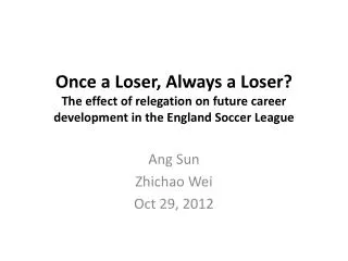
Example 1 : multi-target electromagnetic sensing Nan-Wei Gong, Steve Hodges, and Joseph A. Paradiso. 2011. “Leveraging conductive inkjet technology to build a scalable and versatile surface for ubiquitous sensing” (UbiComp '11).
Capacitive Sensing for presence and gait detection Passive Mode Active Shunt Mode
Gait Analysis Different signatures typically detected with the passive capacitive sensing method. (a) Forefoot strike, (b) heel strike pattern (left feet), (c) and (d) mid-swing between steps(right feet), detected by adjacent electrodes. The decay time is from the RC response of the envelope detector.
Cellular signals versus localization and identification 13.56MHz NFC square loop antenna Cutouts on the electrode eliminate Eddy currents that would decrease performance. 900/1800MHz ¼ wavelength GSM antenna • The pattern and signal strength of NFC are consistent and can easily be used to determine range by measuringpeak thresholds. • GSM signals have stronger signal response that can infer longer distance tracking by integrating and averaging the signal patterns.
Example 2 :Ultrasonic Thermometry MAS.836 Final Project (Martin A. Segado) 2011 • Speed of sound in ideal gas (~air) is • Spaced ultrasound pair in feedback loop: • So, can compute temperature as: K Ideally, 1-PointCalibration
Ultrasonic Thermometry MAS.836 Final Project (Martin A. Segado) 2011 Temperature Probe Transmitter Receiver (mostly hidden by tape)