Download
1 / 36
360 likes | 430 Views
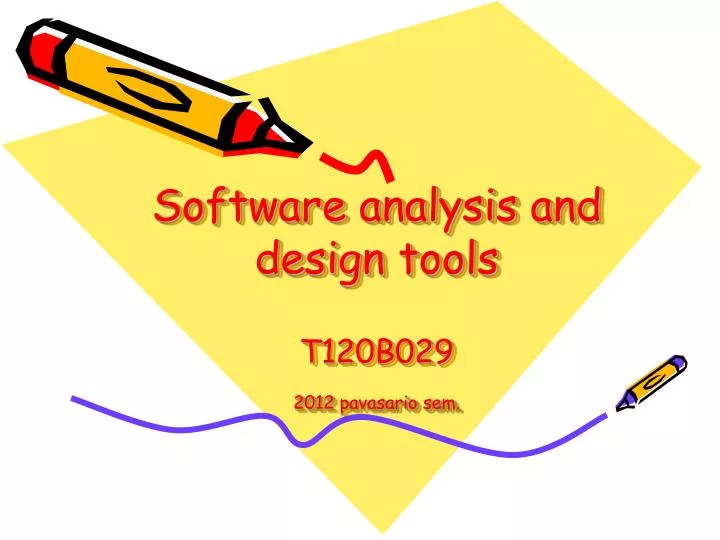
Software analysis and design tools T120B029 20 12 pavasario sem. Instructor: Eduardas Bareiša , Professor Department of Software Engineering Studentų 50-406 Office Hours: Monday 8 :00 - 1 0 :00, Fri day 8 :00 - 1 0 :00 Lectures Hours: Thursday 1 0:00 - 11:45; Labs Hours:

E N D
Software analysis and design toolsT120B0292012 pavasario sem.
Instructor: Eduardas Bareiša,Professor Department of Software EngineeringStudentų 50-406Office Hours: Monday8:00 - 10:00, Friday 8:00 - 10:00 Lectures Hours: Thursday 10:00 - 11:45; Labs Hours: Thursday: 14:15 - 19:15; phone: +370 37 300361email: edas@soften.ktu.ltwww. soften.ktu.lt/~edas/t120b029 T120B029
Textbooks • Craig Larman, Applying UML and Patterns: An Introduction to Object-Oriented Analysis and Design and the Unified Process ,2/e (ISBN: 0130925691) • Ian Sommerville, Software Engineering 6th Edition T120B029
LINKS • http://www.dotnetcoders.com/web/learning/uml/default.aspx • http://www.johndeacon.net/UML/UML_Appendix/Generated/UML_Appendix.asp • http://www.cs.queensu.ca/Software-Engineering/toolcat.html T120B029
Requirements Elicitation Requirements Analysis System Design Object Design Implemen- tation Testing Implemented By Expressed in Terms Of Structured By Realized By Verified By class... class... class... ? ? class.... Application Domain Objects Implementation Domain Objects Use Case Model Source Code SubSystems Test Cases Software Lifecycle Activities T120B029
Requirements Elicitation system specification :Model Analysis analysis model :Model Products of Requirements Process T120B029
Modeling with UML T120B029
Why model software? Software is already an abstraction: why model software? Software is getting larger, not smaller • NT 5.0 ~ 40 million lines of code • A single programmer cannot manage this amount of code in its entirety. • Code is often not directly understandable by developers who did not participate in the development • We need simpler representations for complex systems • Modeling is a mean for dealing with complexity T120B029
Application and Solution Domain • Application Domain (Requirements Analysis): • The environment in which the system is operating • Solution Domain (System Design, Object Design): • The available technologies to build the system T120B029
What is UML? • UML (Unified Modeling Language) • An emerging standard for modeling object-oriented software. • Resulted from the convergence of notations from three leading object-oriented methods: • OMT (James Rumbaugh) • OOSE (Ivar Jacobson) • Booch (Grady Booch) • Supported by several CASE tools • Rational ROSE • Microsoft Visio • ... T120B029
UML and This Course • You can model 80% of most problems by using about 20% UML • In this course, we teach you those 20% T120B029
UML First Pass • Use case diagrams • Describe the functional behavior of the system as seen by the user. • Class diagrams • Describe the static structure of the system: Objects, Attributes, and Associations. • Sequence diagrams • Describe the dynamic behavior between actors and the system and between objects of the system. • Statechart diagrams • Describe the dynamic behavior of an individual object as a finite state machine. • Activity diagrams • Model the dynamic behavior of a system, in particular the workflow, i.e. a flowchart. T120B029
UML First Pass: Class Diagrams Class Multiplicity Association SimpleWatch 1 1 1 1 1 2 1 2 PushButton state push()release() LCDDisplay Battery load() Time now() blinkIdx blinkSeconds() blinkMinutes() blinkHours() stopBlinking() referesh() Attributes Operations Class diagrams represent the structure of the system T120B029
Concepts In Software: Type and Instance • Type: • An abstraction in the context of programming languages • Name: int, Purpose: integral number, Members: 0, -1, 1, 2, -2, . . . • Instance: • Member of a specific type • The type of a variable represents all possible instances the variable can take. • Abstract data type: • Special type whose implementation is hidden from the rest of the system. T120B029
TariffSchedule Table zone2price Enumeration getZones() Price getPrice(Zone) TariffSchedule zone2price getZones() getPrice() TariffSchedule Classes Name Signature Attributes Operations • A class represent a concept. • A class encapsulates state (attributes) and behavior (operations). • Each attribute has a type. • Each operation has a signature. • The class name is the only mandatory information. T120B029
Instances tariff_1974:TarifSchedule zone2price = { {‘1’, .20},{‘2’, .40}, {‘3’, .60}} • An instance represents a phenomenon. • The name of an instance is underlined and can contain the class of the instance. • The attributes are represented with their values. T120B029
TripLeg pricezone Associations TarifSchedule Enumeration getZones() Price getPrice(Zone) * * • Associations denote relationships between classes. • The multiplicity of an association end denotes how many objects the source object can legitimately reference. • Associations should be named (added by Hartrum) T120B029
Country City 1 1 Has-capital name:String name:String Point x:Integer y:Integer Polygon 1 * draw() 1-to-1 and 1-to-Many Associations 1-to-1 association 1-to-many association T120B029
File 1 * Directory filename 0..1 1 Directory File filename Qualification • The qualifier improves the information about the multiplicity of the association between the classes. • It is used for reducing 1-to-many multiplicity to 1-1 multiplicity Without qualification: A directory has many files. A file belongs only to one directory. With qualification: A directory has many files, each with a unique name T120B029
Exhaust System Tailpipe Muffler Aggregation • An aggregation is a special case of association denoting a “consists of” hierarchy. • The aggregate is the parent class, the components are the children class. 1 0..2 T120B029
TicketMachine 3 ZoneButton Composition • A solid diamond denote composition, a strong form of aggregation where components cannot exist without the aggregate. T120B029
Button CancelButton ZoneButton Generalization • Generalization relationships denote inheritance between classes. • The children classes inherit the attributes and operations of the parent class. • Generalization simplifies the model by eliminating redundancy. T120B029
Object Types • Entity Objects • Represent the persistent information tracked by the system (Application domain objects, “Business objects”) • Boundary Objects • Represent the interaction between the user and the system • Control Objects: • Represent the control tasks performed by the system • Having three types of objects leads to models that are more resilient to change. • The boundary of a system changes more likely than the control • The control of the system change more likely than the application domain • Object types originated in Smalltalk: • Model, View, Controller (MV) T120B029
<<entity>> <<control>> <<boundary>> Year ChangeDateControl ButtonBoundary <<entity>> <<boundary>> Month LCDDisplayBoundary <<entity>> Day Example: 2BWatch Objects • UML provides several mechanisms to extend the language • UML provides the stereotype mechanism to present new modeling elements T120B029
Finding Participating Objects in Use Cases • For any use case do the following • Find terms that developers or users need to clarify in order to understand the flow of events • Always start with the user’s terms, then negotiate: • FieldOfficerStationBoundary or FieldOfficerStation? • IncidentBoundary or IncidentForm? • EOPControl or EOP? • Identify real world entities that the system needs to keep track of. Examples: FieldOfficer, Dispatcher, Resource • Identify real world procedures that the system needs to keep track of. Example: EmergencyOperationsPlan • Identify data sources or sinks. Example: Printer • Identify interface artifacts. Example: PoliceStation • Do textual analysis to find additional objects (Use Abott’s technique) • Model the flow of events with a sequence diagram T120B029
:SimpleWatch :LCDDisplay :Time :WatchUser pressButton1() blinkHours() pressButton1() blinkMinutes() pressButton2() incrementMinutes() refresh() pressButtons1And2() commitNewTime() stopBlinking() UML First Pass: Sequence Diagram Object Message Activation Sequence diagrams represent the behavior as interactions T120B029
Sequence Diagram Observations • UML sequence diagrams represent behavior in terms of interactions. • Complement the class diagrams which represent structure. • Useful to find participating objects. • Time consuming to build but worth the investment. T120B029
Increment Hours button2Pressed button1&2Pressed Blink Hours button1Pressed Increment Minutes button2Pressed button1&2Pressed Blink Minutes button1Pressed Increment Seconds button2Pressed Blink Stop Blinking Seconds UML First Pass: Statechart Diagrams State Initial state Event Transition button1&2Pressed Final state T120B029
Activity Diagrams • An activity diagram shows flow control within a system • An activity diagram is a special case of a state chart diagram in which states are activities (“functions”) • Two types of states: • Action state: • Cannot be decomposed any further • Happens “instantaneously” with respect to the level of abstraction used in the model • Activity state: • Can be decomposed further • The activity is modeled by another activity diagram T120B029
Activity Diagram: Modeling Decisions T120B029
Allocate Resources Open Coordinate Archive Incident Resources Incident Document Incident Activity Diagrams: Modeling Concurrency • Synchronization of multiple activities • Splitting the flow of control into multiple threads Splitting Synchronization T120B029
Dispatcher Allocate Resources Open Coordinate Archive Incident Resources Incident FieldOfficer Document Incident Activity Diagrams: Swimlanes • Actions may be grouped into swimlanes to denote the object or subsystem that implements the actions. T120B029
Other UML Notations UML provide other notations that we will be introduced in subsequent lectures, as needed. • Implementation diagrams • Component diagrams • Deployment diagrams • Introduced in lecture on System Design • Object Constraint Language (OCL) • Introduced in lecture on Object Design T120B029
Summary • UML provides a wide variety of notations for representing many aspects of software development • Powerful, but complex language • Can be misused to generate unreadable models • Can be misunderstood when using too many exotic features • We concentrate only on a few notations: • Functional model: use case diagram • Object model: class diagram • Dynamic model: sequence diagrams, statechart and activity diagrams T120B029
Analysis: UML Activity Diagram T120B029
Requirements Analysis Document Template 1. Introduction 2. Current system 3. Proposed system 3.1 Overview 3.2 Functional requirements 3.3 Nonfunctional requirements 3.4 Constraints (“Pseudo requirements”) 3.5 System models 3.5.1 Scenarios 3.5.2 Use case model 3.5.3 Object model 3.5.3.1 Data dictionary 3.5.3.2 Class diagrams 3.5.4 Dynamic models 3.5.5 User interface 4. Glossary T120B029