Download
1 / 35
350 likes | 490 Views
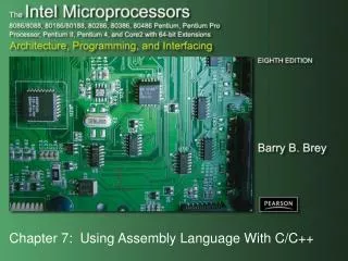
Chapter 7 Assembly Language An Hong han@ustc.edu.cn 2016 Fall. School of Computer Science and Technology. Lecture on Introduction to Computing Systems. Review:The Transistor & Digital Logic. 2019/11/2. 2. Review: Von Neumann Model. Review:The ISA. 2019/11/2. 4.

E N D
Chapter 7 Assembly LanguageAn Honghan@ustc.edu.cn2016 Fall School of Computer Science and Technology Lecture on Introduction to Computing Systems
Review:The Transistor & Digital Logic 2019/11/2 2
Review:TheISA 2019/11/2 4
Review:TheData Path(von Neumann Model) 2019/11/2 5
Review:TheState Machine(Turing Machine equivalent) 2019/11/2 6
A LC-3 Program • X4101 • X4102 • X4103 • X4104 • X4105 • X4106 • X4107 • X4108 • X4109 • X410A • X410B • X410C • X410D • X410E • X410F • X4110 • X4101 • X4102 • X4103 • X4104 • 0 1 0 1 0 1 0 0 1 0 1 0 0 0 0 0 • 0 0 1 0 0 1 1 0 0 0 0 1 0 0 0 0 • 1 1 1 1 0 0 0 0 0 0 1 0 0 0 1 1 • 0 1 1 0 0 0 1 0 1 1 0 0 0 0 0 0 • 0 0 0 1 1 0 0 0 0 1 1 1 1 1 0 0 • 0 0 0 0 0 1 0 0 0 0 0 0 1 0 0 0 • 1 0 0 1 0 0 1 0 0 1 1 1 1 1 1 1 • 0 0 0 1 0 0 1 0 0 1 1 0 0 0 0 1 • 0 0 0 1 0 0 1 0 0 1 0 0 0 0 0 0 • 0 0 0 0 1 0 1 0 0 0 0 0 0 0 0 1 • 0 0 0 1 0 1 0 0 1 0 1 0 0 0 0 1 • 0 0 0 1 0 1 1 0 1 1 1 0 0 0 0 1 • 0 1 1 0 0 0 1 0 1 1 0 0 0 0 0 0 • 0 0 0 0 1 1 1 1 1 1 1 1 0 1 1 0 • 0 0 1 0 0 0 0 0 0 0 0 0 0 1 0 0 • 0 0 0 1 0 0 0 0 0 0 0 0 0 0 1 0 • 1 1 1 1 0 0 0 0 0 0 1 0 0 0 0 1 • 1 1 1 1 0 0 0 0 0 0 1 0 0 1 0 1 • 1 0 0 0 0 0 0 0 0 0 0 0 0 0 0 1 • 0 0 0 0 0 0 0 0 0 0 1 1 0 0 0 0 • X8001 • X8002 • X8003 • X8004 • X8005 • X8006 • X8007 • X8008 • X8009 • X800A • X800B • X800C • X800D • X800E • X800F • X8010 • X8011 • X8012 • X8013 • X8014 • X8015 • X8016 • X8017 • X8018 • 0 0 0 0 0 0 0 0 0 1 0 0 1 1 0 0 • 0 0 0 0 0 0 0 0 0 1 0 0 1 0 1 0 • 0 0 0 0 0 0 0 0 0 1 0 1 0 0 0 1 • 0 0 0 0 0 0 0 0 0 1 0 0 1 1 0 0 • 0 0 0 0 0 0 0 0 0 1 0 1 0 1 1 0 • 0 0 0 0 0 0 0 0 0 1 0 0 1 0 0 1 • 0 0 0 0 0 0 0 0 0 1 0 0 0 0 0 1 • 0 0 0 0 0 0 0 0 0 1 0 1 0 0 1 1 • 0 0 0 0 0 0 0 0 0 1 0 1 0 1 1 0 • 0 0 0 0 0 0 0 0 0 1 0 0 0 0 0 0 • 0 0 0 0 0 0 0 0 0 1 0 0 0 0 0 0 • 0 0 0 0 0 0 0 0 0 1 0 0 0 0 0 0 • 0 0 0 0 0 0 0 0 0 1 0 1 0 1 1 0 • 0 0 0 0 0 0 0 0 0 1 0 0 1 0 0 1 • 0 0 0 0 0 0 0 0 0 1 0 1 1 0 0 0 • 0 0 0 0 0 0 0 0 0 1 0 0 1 1 0 0 • 0 0 0 0 0 0 0 0 0 1 0 0 0 0 0 0 • 0 0 0 0 0 0 0 0 0 1 0 0 1 0 0 0 • 0 0 0 0 0 0 0 0 0 1 0 0 1 1 1 0 • 0 0 0 0 0 0 0 0 0 1 0 0 0 0 0 0 • 0 0 0 0 0 0 0 0 0 0 0 0 0 1 0 0 • 0 0 0 0 0 0 0 0 0 1 0 0 0 0 0 0 • 0 0 0 0 0 0 0 0 0 1 0 1 1 0 1 0 • 0 0 0 0 0 0 0 0 0 0 0 0 0 10 0
Human-Readable Machine Language • Computers like ones and zeros… • Humans like symbols… • Assembler is a program that turns symbols intomachine instructions. • ISA-specific:close correspondence between symbols and instruction set • mnemonics for opcodes • labels for memory locations • additional operations for allocating storage and initializing data 0001110010000110 ADD R6,R2,R6 ; increment index reg.
lw $t0, 0($2) lw $t1, 4($2) sw $t1, 0($2) sw $t0, 4($2) How do we get the electrons to do the work? temp = v[k]; v[k] = v[k+1]; v[k+1] = temp; Now, You are Here. High Level LanguageProgram (e.g., C) Compiler Anything can be representedas a number, i.e., data or instructions Assembly Language Program (e.g., MIPS) Assembler 0000 1001 1100 0110 1010 1111 0101 1000 1010 1111 0101 1000 0000 1001 1100 0110 1100 0110 1010 1111 0101 1000 0000 1001 0101 1000 0000 1001 1100 0110 1010 1111 Machine Language Program (MIPS) Machine Interpretation Hardware Architecture Description(e.g., block diagrams) Architecture Implementation Logic Circuit Description(Circuit Schematic Diagrams) Lecture 1
Big Idea #2: How do we get the electrons to do the work? Application Algorithm & Data Structure Now, You are Here. Language Software 指令集体系结构(Machine Architecture, ISA) Hardware Microarchiture Logic and IC Device Computer System: Layers of Abstraction
Abstraction Layers in Modern Systems USTC Courses Now, You are Here. Application 算法基础/数据结构 Algorithm and Data Structure 程序设计/编译技术 Programming Language/Compiler 操作系统/虚拟机 Operating System/Virtual Machines Instruction Set Architecture (ISA) 计算机组成 Microarchitecture 数字逻辑 Gates/Register-Transfer Level (RTL) Analog/Digital Circuits 集成电路 Electronic Devices 微电子 Physics Lecture 1 11
An Assembly Language Program ; ; Program to multiply a number by the constant 6 ; .ORIG x3050 LD R1, SIX LD R2, NUMBER AND R3, R3, #0 ; Clear R3. It will ; contain the product. ; The inner loop ; AGAIN ADD R3, R3, R2 ADD R1, R1, #-1 ; R1 keeps track of BRp AGAIN ; the iteration. ; HALT ; NUMBER .BLKW 1 SIX .FILL x0006 ; .END
LC-3 Assembly Language Syntax • Each line of a program is one of the following: • an instruction • an assember directive (or pseudo-op) • a comment • Whitespace (between symbols) and case are ignored. • Comments (beginning with “;”) are also ignored. • An instruction has the following format: LABEL OPCODE OPERANDS COMMENTS optional mandatory
Opcodes and Operands • Opcodes • reserved symbols that correspond to LC-3 instructions • listed in Appendix A • ex: ADD, AND, LD, LDR, … • Operands • registers -- specified by Rn, where n is the register number • numbers -- indicated by # (decimal) or x (hex) • label -- symbolic name of memory location • separated by comma • number, order, and type correspond to instruction format • ex: ADD R1,R1,R3 ADD R1,R1,#3 LD R6,NUMBER BRz LOOP
Labels and Comments • Label • placed at the beginning of the line • assigns a symbolic name to the address corresponding to line • ex:LOOP ADD R1,R1,#-1BRp LOOP • Comment • anything after a semicolon is a comment • ignored by assembler • used by humans to document/understand programs • tips for useful comments: • avoid restating the obvious, as “decrement R1” • provide additional insight, as in “accumulate product in R6” • use comments to separate pieces of program
Assembler Directives • Pseudo-operations • do not refer to operations executed by program • used by assembler • look like instruction, but “opcode” starts with dot
Trap Codes • LC-3 assembler provides “pseudo-instructions” foreach trap code, so you don’t have to remember them.
Style Guidelines • Use the following style guidelines to improvethe readability and understandability of your programs: • Provide a program header, with author’s name, date, etc.,and purpose of program. • Start labels, opcode, operands, and comments in same columnfor each line. (Unless entire line is a comment.) • Use comments to explain what each register does. • Give explanatory comment for most instructions. • Use meaningful symbolic names. • Mixed upper and lower case for readability. • ASCIItoBinary, InputRoutine, SaveR1 • Provide comments between program sections. • Each line must fit on the page -- no wraparound or truncations. • Long statements split in aesthetically pleasing manner.
Sample Program • Count the occurrences of a character in a file.Remember this?
Char Count in Assembly Language (1 of 3) ; ; Program to count occurrences of a character in a file. ; Character to be input from the keyboard. ; Result to be displayed on the monitor. ; Program only works if no more than 9 occurrences are found. ; ; ; Initialization ; .ORIG x3000 AND R2, R2, #0 ; R2 is counter, initially 0 LD R3, PTR ; R3 is pointer to characters GETC ; TRAP x23 ; R0 gets character input LDR R1, R3, #0 ; R1 gets first character ; ; Test character for end of file ; TEST ADD R4, R1, #-4 ; Test for EOT (ASCII x04) BRz OUTPUT ; If done, prepare the output
Char Count in Assembly Language (2 of 3) ; ; Test character for match. If a match, increment count. ; NOT R1, R1 ADD R1, R1, R0 ; If match, R1 = xFFFF NOT R1, R1 ; If match, R1 = x0000 BRnp GETCHAR ; If no match, do not increment ADD R2, R2, #1 ; ; Get next character from file. ; GETCHAR ADD R3, R3, #1 ; Point to next character. LDR R1, R3, #0 ; R1 gets next char to test BRnzp TEST ; ; Output the count. ; OUTPUT LD R0, ASCII ; Load the ASCII template ADD R0, R0, R2 ; Covert binary count to ASCII OUT ; TRAP x21 ; ASCII code in R0 is displayed. HALT ; TRAP x25,Halt machine
Char Count in Assembly Language (3 of 3) ; ; Storage for pointer and ASCII template ; ASCII .FILL x0030 PTR .FILL x9000 .END
Assembly Process • Convert assembly language file (.asm)into an executable file (.obj) for the LC-3 simulator. • First Pass: • scan program file • find all labels and calculate the corresponding addresses;this is called the symbol table • Second Pass: • convert instructions to machine language,using information from symbol table
First Pass: Constructing the Symbol Table • Find the .ORIG statement,which tells us the address of the first instruction. • Initialize location counter (LC), which keeps track of thecurrent instruction. • For each non-empty line in the program: • If line contains a label, add label and LC to symbol table. • Increment LC. • NOTE: If statement is .BLKW or .STRINGZ,increment LC by the number of words allocated. • Stop when .END statement is reached. • NOTE: A line that contains only a comment is considered an empty line.
Practice • Construct the symbol table for the program in Figure 7.1(Slides 7-11 through 7-13).
Practice • Construct the symbol table for the program in Figure 7.1(Slides 7-11 through 7-13).
Second Pass: Generating Machine Language • For each executable assembly language statement,generate the corresponding machine language instruction. • If operand is a label,look up the address from the symbol table. • Potential problems: • Improper number or type of arguments • ex: NOT R1,#7 ADD R1,R2 ADD R3,R3,NUMBER • Immediate argument too large • ex: ADD R1,R2,#1023 • Address (associated with label) not on the same page • can’t use direct addressing mode
Practice • Using the symbol table constructed earlier,translate these statements into LC-3 machine language. • (Assume all addresses are on the current page.)
LC-3 Assembler • Using “assemble” (Unix) or LC3 Edit (Windows),generates several different output files. This one getsloaded into thesimulator.
Object File Format • LC-3 object file contains • Starting address (location where program must be loaded),followed by… • Machine instructions • Example • Beginning of “count character” object file looks like this: 0011000000000000010101001010000000100110000101001111000000100011... .ORIG x3000 AND R2, R2, #0 LD R3, PTR TRAP x23
Multiple Object Files • An object file is not necessarily a complete program. • system-provided library routines • code blocks written by multiple developers • For LC-3, can load multiple object files into memory,then start executing at a desired address. • system routines, such as keyboard input, are loaded automatically • loaded into “system memory,” below x1000 • by convention, user code should be loaded betweenx3000 and xCFFF • each object file includes a starting address • be careful not to load overlapping object files
Linking and Loading • Loading is the process of copying an executable imageinto memory. • more sophisticated loaders are able to relocate imagesto fit into available memory • must readjust branch targets, load/store addresses • Linking is the process of resolving symbols betweenindependent object files. • suppose we define a symbol in one module,and want to use it in another • some notation, such as .EXTERNAL, is used to tell assembler that a symbol is defined in another module • linker will search symbol tables of other modules to resolve symbols and complete code generation before loading
Memory map of the LC-3 0x0000 Trap Vector Table 0x00FF 0x0100 Interrupt Vector Table 0x01FF 0x0200 Operating System and Supervisor Stack 0x2FFF PC 0x3000 Program Text R6 Function1 R4(Global pointer) R5 Global data section R6 Function2 Heap (for dynamically allocated memory) R5 R6 Function3 R6 (stack pointer) Run-time stack R5 R5 (frame pointer) 0xFDFF 0xFE00 Device Register Addresses 0xFFFF
lw $t0, 0($2) lw $t1, 4($2) sw $t1, 0($2) sw $t0, 4($2) Summary: Assembly Language temp = v[k]; v[k] = v[k+1]; v[k+1] = temp; Now, You are Here. High Level LanguageProgram (e.g., C) Compiler Anything can be representedas a number, i.e., data or instructions Assembly Language Program (e.g., MIPS) Assembler 0000 1001 1100 0110 1010 1111 0101 1000 1010 1111 0101 1000 0000 1001 1100 0110 1100 0110 1010 1111 0101 1000 0000 1001 0101 1000 0000 1001 1100 0110 1010 1111 Machine Language Program (MIPS) Machine Interpretation Hardware Architecture Description(e.g., block diagrams) ALUOP[0:3] <= InstReg[9:11] & MASK Architecture Implementation Logic Circuit Description(Circuit Schematic Diagrams) Lecture 1
Big Idea #2: How do we get the electrons to do the work? Application Algorithm & Data Structure Now, You are Here. Language Software 指令集体系结构(Machine Architecture, ISA) Hardware Microarchiture Logic and IC Device Computer System: Layers of Abstraction