Download
1 / 13
180 likes | 886 Views
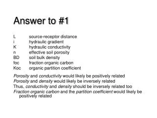
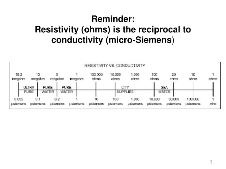
Reminder: Resistivity (ohms) is the reciprocal to conductivity (micro-Siemens ). 1. BEWARE of Biofilm Buildup. 164. SOURCE: http://www.fda.gov/ICECI/Inspections/InspectionGuides/ucm074905.htm. Process Water System Design Phase. Assemble cross-functional team Determine quality of feed water

E N D
Reminder: Resistivity (ohms) is the reciprocal to conductivity (micro-Siemens) 1
BEWARE of Biofilm Buildup 164 SOURCE: http://www.fda.gov/ICECI/Inspections/InspectionGuides/ucm074905.htm
Process Water SystemDesign Phase Assemble cross-functional team Determine quality of feed water Determine required specifications Write protocols Pre-validation Calibration of instruments Validation of test methods 3
Purified Water System Design Considerations 316LSS material of construction Sanitary electro-polishing and passivation Sanitary clamp fittings or orbital welds Lines sloped to drain 1/8 in/ft Recirculation loop 3-5ft/sec Sanitary pumps, Submicron filters (0.2μm) on tanks and vents Use-point fittings or GMP valves Sanitary diaphragm-type and stem valves only. No ball, gate, plug, butterfly, globe or disc valves. Drains must have air-break to prevent back-siphoning Minimize dead-legs to 6D Control biofilm buildup (recirculation, 85oC, ozonation) No added substances SOURCE: Manfredi, Joe, “Myths, Rumors, Fantasies about Water System Design”, Pharmaceutical Technology CGMP Compliance 2006, pp 28-38 4
Typical deionizer schematic from water softener HCl NaOH 6 6 5 5 4 4 3 3 2 2 1 1 Water must be kept circulating Anionic column Cartridge filter 5 µm Cartridge filter 1 µm Cationic column UV light Eluates to neutralization plant Ozone generator Hygienic pump Return to deioniczer Outlets or storage. Drain line Air break to sewer Water for Pharmaceutical Use
Installation Qualification Assure that the system is installed per design criteria Test water before and after each piece of equipment in-line. Not just at point-of-use! Use that data to write your SOPs (backflushing, regeneration, etc.) For example . . . 6
Qualification of Mixed Bed Deionizers Conductivity PSID (scaling) Run length gallonage Amount of regenerate Rinse water gallonage Silica (channeling) Bacterial load Other (eg. Air quality) In-Use Regeneration Dilute Base Monitor feed water and effluent Cation & Anion Mixed Bed Anion Cation Purified Process Water Air Dilute Acid To Waste Mixed bed regeneration requires backwashing for separate treatment with acid and base. They are mixed with air before start-up. 7
Operation Qualification Is the system operating correctly? Pumps at right pressure? Water flow correct? Continue to test feed water, sample ports and points-of-use Monitor system changes to validate the SOPs 8
Water Validation and the Corporate Audit Allow extra time to audit the water system Trained persons are needed to maintain the water system Must check for specifications and acceptance criteria for each sampling point 9
Water for Process Use Designed, constructed and validated to prevent microbial proliferation and assure quality SOPs for maintenance, cleaning & sanitization on frequent basis Monitor & test to assure conformance to chemical, physical and microbiological specifications Sanitary sampling portsafter each component Check at point-of-use daily Record & document test results Alert & action limits Corrective action plan 10
Performance Qualification Test all sample ports for 30 consecutive days (spring, summer, fall and winter) Validation complete after one full year Trend analysis may help avoid having to revalidate Develop change control procedures Establish acceptance criteria for each piece of equipment Establish alert and action limits Develop corrective action plans Confirm the action had the desired affect 11