Download
1 / 170
2.36k likes | 3.47k Views
PHYSICS Principles and Problems. Chapter 25: Electromagnetic Induction. Electromagnetic Induction. CHAPTER 25. BIG IDEA. A changing magnetic field can induce current in a conductor. Table Of Contents. CHAPTER 25. Section 25.1 Inducing Currents

E N D
PHYSICS Principles and Problems Chapter 25: Electromagnetic Induction
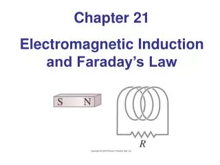
Electromagnetic Induction CHAPTER25 BIG IDEA A changing magnetic field can induce current in a conductor.
Table Of Contents CHAPTER25 Section 25.1Inducing Currents Section 25.2Application of Induced Currents Click a hyperlink to view the corresponding slides. Exit
Inducing Currents SECTION25.1 MAIN IDEA A changing magnetic field induces an EMF in a wire, and in turn generates current when the wire is in a circuit. • What is induced EMF? • What affects the induced EMF current produced by a changing magnetic field? • How does a generator produce electrical energy? • How are the effective current and effective potential difference related to the maximum values of those quantities in an AC circuit? Essential Questions
New Vocabulary Electromagnetic induction Induced electromotive force Electric generator Inducing Currents SECTION25.1 • Review Vocabulary • Potential difference the work needed to move a positive test charge from one point to another divided by the magnitude of the test charge
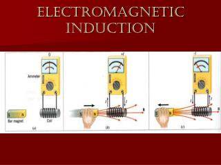
Inducing Currents SECTION25.1 Changing Magnetic Fields • In Chapter 24, you learned how Hans Christian Oersted discovered that an electric current produces a magnetic field. • Michael Faraday thought that the reverse must also be true: that a magnetic field produces an electric current. • In 1822, Michael Faraday wrote a goal in his notebook: “Convert magnetism into electricity.” • Faraday tried many combinations of magnetic fields and wires without success.
Inducing Currents SECTION25.1 Changing Magnetic Fields (cont.) • After nearly ten years of unsuccessful experiments, Faraday found that he could induce electric current by moving a wire through a magnetic field. • In the same year, Joseph Henry, an American high-school teacher, also showed that a changing magnetic field could produce electric current. • Henry took an idea developed by another scientist and broadened the application to other educational demonstration devices to make them more sensitive or powerful.
Inducing Currents SECTION25.1 Changing Magnetic Fields (cont.) Click image to view the movie.
Inducing Currents SECTION25.1 Changing Magnetic Fields (cont.) • When you studied electric circuits, you learned that a source of electrical energy, such as a battery, is needed to produce a continuous current. • The potential difference, or voltage, given to the charges by a battery is called the electromotive force, or EMF. • Electromotive force, however, is not actually a force; instead, it is a potential difference and is measured in volts. • Thus, the term electromotive force is misleading.
Inducing Currents SECTION25.1 Changing Magnetic Fields (cont.) • Like many other historical terms still in use, it originated before the related principles—in this case, those of electricity— were well understood. • The EMF is the influence that makes current flow from lower to higher potential. • What created the potential difference that caused an induced current in Faraday’s experiment? • When you move a wire through a magnetic field, you exert a force on the charges and they move in the direction of the force.
Inducing Currents SECTION25.1 Changing Magnetic Fields (cont.) • Work is done on the charges. Their electrical potential energy, and thus their potential, is increased. • The difference in potential is called the induced EMF. • EMF depends on the magnetic field, B, the length of the wire in the magnetic field, L, and the velocity of the wire in the field that is perpendicular to the field, v(sin θ). Electromotive ForceEMF = BLv(sin θ)
Inducing Currents SECTION25.1 Changing Magnetic Fields (cont.) • If a wire moves through a magnetic field at an angle to the field, only the component of the wire’s velocity that is perpendicular to the direction of the magnetic field generates EMF. • If the wire moves through the field with a velocity that is exactly perpendicular to the field, then the equation reduces to EMF = BLv, because sin 90° = 1.
Inducing Currents SECTION25.1 Changing Magnetic Fields (cont.) • Checking the units of the EMF equation will help you work algebra correctly in related problems. • The unit for measuring EMF is the volt, V. • In Chapter 24, B was defined as F/IL; therefore, the units for B are N/A·m. • Velocity is measured in m/s. Using dimensional analysis, (N/A·m)(m)(m/s) = N·m/A·s = J/C = V. • Recall from previous chapters that J = N·m, A = C/s, and V = J/C.
Inducing Currents SECTION25.1 Changing Magnetic Fields (cont.) • A microphone is a simple application that depends on an induced EMF. • A dynamic microphone is similar in construction to a loudspeaker. • The microphone shown in the figure has a diaphragm attached to a coil of wire that is free to move in a magnetic field.
Inducing Currents SECTION25.1 Changing Magnetic Fields (cont.) • Sound waves vibrate the diaphragm, which moves the coil in the magnetic field. • The motion of the coil, in turn, induces an EMF across the ends of the coil. • The induced EMF varies as the frequency of the sound varies. In this way, the sound wave is converted to an electrical signal. • The voltage generated is small, typically 10-3 V, but it can be increased, or amplified, by electronic devices.
Inducing Currents SECTION25.1 Induced EMF A straight wire, 0.20 m long, moves at a constant speed of 7.0 m/s perpendicular to a magnetic field of strength 8.0×10⁻² T. • a. What EMF is induced in the wire? • b. The wire is part of a circuit that has a resistance of 0.50 Ω. What is the current through the wire? • c. If a different metal was used for the wire, which has a resistance of 0.78 Ω, what would the new current be?
Inducing Currents SECTION25.1 Induced EMF (cont.) Step 1: Analyze and Sketch the Problem
Inducing Currents SECTION25.1 Induced EMF (cont.) Establish a coordinate system. Draw a straight wire of length L. Choose a direction for the magnetic field that is perpendicular to the length of wire.
Inducing Currents SECTION25.1 Induced EMF (cont.) Connect an ammeter to the wire to represent a measurement of current.
Inducing Currents SECTION25.1 Induced EMF (cont.) Choose a direction for the velocity that is perpendicular to both the length of the wire and the magnetic field.
Inducing Currents SECTION25.1 Induced EMF (cont.) Identify the known and unknown variables. Known: v = 7.0 m/s L = 0.20 m B = 8.0×10⁻² T R1 = 0.50 Ω R2 = 0.78 Ω Unknown: EMF = ? I = ?
Inducing Currents SECTION25.1 Induced EMF (cont.) Step 2: Solve for the Unknown
Inducing Currents SECTION25.1 Induced EMF (cont.) a.EMF = BLv Substitute B = 8.0×10⁻² T, L = 0.20 m, v = 7.0 m/s EMF = (8.0×10⁻² T)(0.20 m)(7.0 m/s) EMF = 0.11 T·m2/s EMF = 0.11 V
Inducing Currents b. SECTION25.1 Induced EMF (cont.) Substitute V = EMF
Inducing Currents SECTION25.1 Induced EMF (cont.) Substitute EMF = 0.11 V, R1= 0.50 Ω = 0.22 A Using the fourth right-hand rule, the direction of the current is counterclockwise.
Inducing Currents c. SECTION25.1 Induced EMF (cont.) Substitute EMF = 0.11 V, R2= 0.78 Ω = 0.14 A The current is counterclockwise.
Inducing Currents SECTION25.1 Induced EMF (cont.) Step 3: Evaluate the Answer
Inducing Currents SECTION25.1 Induced EMF (cont.) Are the units correct? Volt is the correct unit for EMF. Current is measured in amperes. Does the direction make sense? The direction obeys the fourth right-hand rule: v is the direction of the thumb, B is the same direction as the fingers, and F is the direction that the palm faces. Current is in the same direction as the force.
Inducing Currents SECTION25.1 Induced EMF (cont.) Is the magnitude realistic? The answers are near 10−1. This agrees with the quantities given and the algebra performed.
Inducing Currents SECTION25.1 Induced EMF (cont.) The steps covered were: Step 1: Analyze and Sketch the Problem Establish a coordinate system. Draw a straight wire of length L. Connect an ammeter to the wire to represent a measurement of current. Choose a direction for the magnetic field that is perpendicular to the length of wire.
Inducing Currents SECTION25.1 Induced EMF (cont.) The steps covered were: Step 1: Analyze and Sketch the Problem Choose a direction for the velocity that is perpendicular to both the length of the wire and the magnetic field.
Inducing Currents SECTION25.1 Induced EMF (cont.) The steps covered were: Step 2: Solve for the Unknown EMF = BLv Step 3: Evaluate the Answer
Inducing Currents SECTION25.1 Electric Generators • The electric generator, invented by Michael Faraday, converts mechanical energy to electrical energy. • An electric generator consists of a number of wire loops placed in a strong magnetic field. • The wire is wound around an iron core to increase the strength of the magnetic field. • The iron and the wires are called the armature, which is similar to that of an electric motor.
Inducing Currents SECTION25.1 Electric Generators (cont.) • The armature is mounted so that it can rotate freely in the magnetic field. As the armature turns, the wire loops cut through the magnetic field lines and induce an EMF. • The EMF developed by the generator depends on the length of the wire rotating in the field. • Increasing the number of loops in the armature increases the wire length which increases the induced EMF. • Only the portion of the wire within the magnetic field induces an EMF.
Inducing Currents SECTION25.1 Electric Generators (cont.) • When a generator is connected in a closed circuit, the induced EMF produces an electric current. • The animation shows a single-loop generator without an iron core. • The direction of the induced current can be found from the third right-hand rule. • As the loop rotates, the strength and the direction of the current change.
Inducing Currents SECTION25.1 Electric Generators (cont.) • The animation below shows the amount of current generated by a rotating wire loop.
Inducing Currents SECTION25.1 Electric Generators (cont.) • The current is greatest when the motion of the loop is perpendicular to the magnetic field. That is, when the loop is in the horizontal position, as shown in the figure. • In this position, the component of the loop’s velocity perpendicular to the magnetic field is greatest.
Inducing Currents SECTION25.1 Electric Generators (cont.) • As the loop rotates from the horizontal to the vertical position, as shown in the figure, it moves through the magnetic field lines at an ever-increasing angle. • Thus, it cuts through fewer magnetic field lines per unit of time, and the current decreases.
Inducing Currents SECTION25.1 Electric Generators (cont.) • When the loop is in the vertical position, the wire segments move parallel to the field and the current is zero. • As the loop continues to turn, the segment that was moving up begins to move down and reverses the direction of the current in the loop. • This change in direction takes place each time the loop turns through 180°.
Inducing Currents SECTION25.1 Electric Generators (cont.) • The current changes smoothly from zero to some maximum value and back to zero during each half-turn of the loop. Then it reverses direction. • A graph of current versus time is shown in the figure.
Inducing Currents SECTION25.1 Electric Generators (cont.) • Does the entire loop contribute to the induced EMF? Look at the figure, where all four sides of the loop are depicted in the magnetic field.
Inducing Currents SECTION25.1 Electric Generators (cont.) • If the fourth right-hand rule is applied to segment ab, the direction of the induced current is toward the side of the wire. • The same applies to segment cd. Thus, no current is induced along the length of the wire in ab or cd. • But in segment bc, the direction of the induced current is from b to c, and in segment ad, the current is from d to a. • Because the conducting loop is rotating in a circular motion, the relative angle between a point on the loop and the magnetic field constantly changes.
Inducing Currents SECTION25.1 Electric Generators (cont.) • The electromotive force can be calculated by the electromotive force equation given earlier, EMF = BLv(sin θ), except that L is now the length of segment bc. • The maximum voltage is induced when a conductor is moving perpendicular to the magnetic field and thus θ = 90°. • Generators, such as those in the chapter opening image, work in a similar fashion.
Inducing Currents SECTION25.1 Electric Generators (cont.) • Potential energy from water stored behind a dam is converted to kinetic energy, which spins the turbines. • The turbines then turn coils of conductors in a magnetic field, thereby inducing an EMF. • Generators and motors are almost identical in construction, but they convert energy in opposite directions. • A generator converts mechanical energy to electrical energy, while a motor converts electrical energy to mechanical energy.
Inducing Currents SECTION25.1 Electric Generators (cont.) • An energy source turns the armature of a generator in a magnetic field at a fixed number of revolutions per second. • In the United States, electric utilities use a 60-Hz frequency, in which the current goes from one direction to the other and back to the first 60 times per second.
Inducing Currents SECTION25.1 Electric Generators (cont.) • The figure shows how an alternating current, AC, in an armature is transmitted to the rest of the circuit. • The brush-slip-ring arrangement permits the armature to turn freely while still allowing the current to pass into the external circuit.
Inducing Currents SECTION25.1 Electric Generators (cont.) • As the armature turns, the alternating current varies between some maximum value and zero, as shown in the graph.
Inducing Currents SECTION25.1 Electric Generators (cont.) • The power produced by a generator is the product of the current and the voltage. • Because both current and voltage vary, the power associated with an alternating current varies.
Inducing Currents SECTION25.1 Electric Generators (cont.) • The figure shows a graph of the power produced by an AC generator. • Note that power is always positive because I and V are either both positive or both negative.
Inducing Currents • Average power, PAC, is half the maximum power; thus, SECTION25.1 Electric Generators (cont.)