Download
1 / 1
10 likes | 129 Views
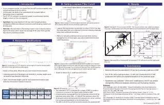
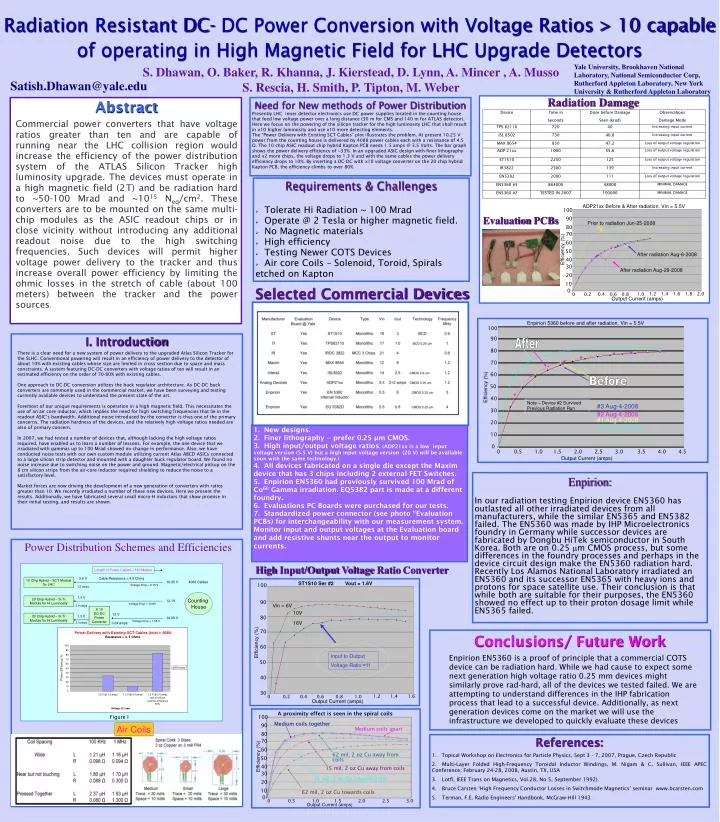
Length of Power Cables = 140 Meters. 3.5 V. Cable Resistance = 4.5 Ohms. 10 Chip Hybrid – SCT Module for LHC. 10.25 V. 4088 Cables. Voltage Drop = 6.75 V. 1.5 amps. Counting House. 1.3 V. 20 Chip Hybrid – Si Tr Module for Hi Luminosity. 12.1V. Voltage Drop = 10.8V. 2.4 amps. 13 V.

E N D
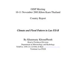
Length of Power Cables = 140 Meters 3.5 V Cable Resistance = 4.5 Ohms 10 Chip Hybrid – SCT Module for LHC 10.25 V 4088 Cables Voltage Drop = 6.75 V 1.5 amps Counting House 1.3 V 20 Chip Hybrid – Si Tr Module for Hi Luminosity 12.1V Voltage Drop = 10.8V 2.4 amps 13 V 20 Chip Hybrid – Si Tr Module for Hi Luminosity 1.3 V 14.08 V Voltage Drop = 1.08 V 2.4 amps 0.24 amps Abstract Commercial power converters that have voltage ratios greater than ten and are capable of running near the LHC collision region would increase the efficiency of the power distribution system of the ATLAS Silicon Tracker high luminosity upgrade. The devices must operate in a high magnetic field (2T) and be radiation hard to ~50-100 Mrad and ~1015 Neq/cm2. These converters are to be mounted on the same multi-chip modules as the ASIC readout chips or in close vicinity without introducing any additional readout noise due to the high switching frequencies. Such devices will permit higher voltage power delivery to the tracker and thus increase overall power efficiency by limiting the ohmic losses in the stretch of cable (about 100 meters) between the tracker and the power sources. Need for New methods of Power Distribution Presently LHC inner detector electronics use DC power supplies located in the counting house that feed low voltage power over a long distance (30 m for CMS and 140 m for ATLAS detector). Here we focus on the powering of the silicon tracker for the high luminosity LHC that shall result in x10 higher luminosity and use x10 more detecting elements. The “Power Delivery with Existing SCT Cables” plot illustrates the problem. At present 10.25 V power from the counting house is delivered by 4088 power cables each with a resistance of 4.5 Ω. The 10 chip ASIC readout chip hybrid Kapton PCB needs 1.5 amps @ 3.5 Volts. The bar graph shows the power delivery efficiency of ~33%. In an upgraded ASIC design with finer lithography and x2 more chips, the voltage drops to 1.3 V and with the same cables the power delivery efficiency drops to 10%. By inserting a DC-DC with x10 voltage converter on the 20 chip hybrid Kapton PCB, the efficiency climbs to over 80%. • Requirements & Challenges • Tolerate Hi Radiation ~ 100 Mrad • Operate @ 2 Tesla or higher magnetic field. • No Magnetic materials • High efficiency • Testing Newer COTS Devices • Air core Coils – Solenoid, Toroid, Spirals etched on Kapton I. Introduction Enpirion: In our radiation testing Enpirion device EN5360 has outlasted all other irradiated devices from all manufacturers, while the similar EN5365 and EN5382 failed. The EN5360 was made by IHP Microelectronics foundry in Germany while successor devices are fabricated by Dongbu HiTek semiconductor in South Korea. Both are on 0.25 mm CMOS process, but some differences in the foundry processes and perhaps in the device circuit design make the EN5360 radiation hard. Recently Los Alamos National Laboratory irradiated an EN5360 and its successor EN5365 with heavy ions and protons for space satellite use. Their conclusion is that while both are suitable for their purposes, the EN5360 showed no effect up to their proton dosage limit while EN5365 failed. References: 1. Topical Workshop on Electronics for Particle Physics, Sept 3 - 7, 2007, Prague, Czech Republic 2. Multi-Layer Folded High-Frequency Toroidal Inductor Windings, M. Nigam & C. Sullivan, IEEE APEC Conference, February 24-28, 2008, Austin, TX, USA 3. Lotfi, IEEE Trans on Magnetics, Vol.28, No 5, September 1992). 4. Bruce Carsten ‘High Frequency Conductor Losses in Switchmode Magnetics’ seminar www.bcarsten.com 5. Terman, F.E. Radio Engineers' Handbook, McGraw-Hill 1943 RadiationResistant DC- DC Power Conversion with Voltage Ratios > 10 capable of operating in High Magnetic Field for LHC Upgrade Detectors Yale University, Brookhaven National Laboratory, National Semiconductor Corp, Rutherford Appleton Laboratory, New York University & Rutherford Appleton Laboratory S. Dhawan, O. Baker, R. Khanna, J. Kierstead, D. Lynn, A. Mincer , A. Musso S. Rescia, H. Smith, P. Tipton, M. Weber Satish.Dhawan@yale.edu Radiation Damage ADP21xx Before & After radiation, Vin = 5.5V 100 Evaluation PCBs 90 Prior to radiation Jun-25-2008 80 70 60 Efficiency (%) 50 After radiation Aug-6-2008 40 30 After radiation Aug-29-2008 20 10 Selected Commercial Devices 0 1.2 1.4 1.6 1.8 2.0 0 1.0 0.2 0.4 0.6 0.8 Output Current (amps) Enpirion 5360 before and after radiation, Vin = 5.5V 100 90 After 80 There is a clear need for a new system of power delivery to the upgraded Atlas Silicon Tracker for the SLHC. Conventional powering will result in an efficiency of power delivery to the detector of about 10% with existing cables whose size are limited in cross section due to space and mass constraints. A system featuring DC-DC converters with voltage ratios of ten will result in an estimated efficiency on the order of 70-80% with existing cables. One approach to DC-DC conversion utilizes the buck regulator architecture. As DC-DC buck converters are commonly used in the commercial market, we have been surveying and testing currently available devices to understand the present state of the art. Foremost of our unique requirements is operation in a high magnetic field. This necessitates the use of an air core inductor, which implies the need for high switching frequencies that lie in the readout ASIC’s bandwidth. Additional noise introduced by the converter is thus one of the primary concerns. The radiation hardness of the devices, and the relatively high voltage ratios needed are also of primary concern. In 2007, we had tested a number of devices that, although lacking the high voltage ratios required, have enabled us to learn a number of lessons. For example, the one device that we irradiated with gammas up to 100 Mrad showed no change in performance. Also, we have conducted noise tests with our own custom module utilizing current Atlas ABCD ASICs connected to a large silicon strip detector and mounted with a daughter buck regulator board. We found no noise increase due to switching noise on the power and ground. Magnetic/electrical pickup on the 8 cm silicon strips from the air-core inductor required shielding to reduce the noise to a satisfactory level. Market forces are now driving the development of a new generation of converters with ratios greater than 10. We recently irradiated a number of these new devices. Here we present the results. Additionally, we have fabricated several small micro-H inductors that show promise in their initial testing, and results are shown. 70 60 Before Efficiency (%) 50 40 Note – Device #2 Survived Previous Radiation Run #3 Aug-4-2008 30 #2 Aug-4-2008 #1 Aug-4-2008 20 #3 Aug-29-2008 1. New designs. 2. Finer lithography -- prefer 0.25 µm CMOS. 3. High input/output voltage ratios. (ADP21xx is a low input voltage version (5.5 V) but a high input voltage version (20 V) will be available soon with the same technology.) 4. All devices fabricated on a single die except the Maxim device that has 3 chips including 2 external FET Switches. 5. Enpirion EN5360 had previously survived 100 Mrad of Co60 Gamma irradiation. EQ5382 part is made at a different foundry. 6. Evaluations PC Boards were purchased for our tests. 7. Standardized power connector (see photo “Evaluation PCBs) for interchangeability with our measurement system. Monitor input and output voltages at the Evaluation board and add resistive shunts near the output to monitor currents. 10 0 0 0.5 1.0 1.5 2.0 2.5 3.0 3.5 4.0 4.5 Output Current (amps) Power Distribution Schemes and Efficiencies High Input/Output Voltage Ratio Converter ST1S10 Ser #2 Vout = 1.6V 100 90 Vin = 6V X 10 DC-DC Power Converter 10V 80 16V 70 Conclusions/ Future Work Efficiency (%) 60 Input to Output Voltage Ratio ≈11 Enpirion EN5360 is a proof of principle that a commercial COTS device can be radiation hard. While we had cause to expect some next generation high voltage ratio 0.25 mm devices might similarly prove rad-hard, all of the devices we tested failed. We are attempting to understand differences in the IHP fabrication process that lead to a successful device. Additionally, as next generation devices come on the market we will use the infrastructure we developed to quickly evaluate these devices 50 40 30 1.2 1.4 1.6 0 1.0 0.2 0.4 0.6 0.8 Output Current (amps) A proximity effect is seen in the spiral coils Figure I 100 Medium coils together 90 Air Coils Medium coils apart 80 70 60 Efficiency (%) 62 mil, 2 oz Cu away from coils 50 40 15 mil, 2 oz Cu away from coils 30 15 mil, 2 oz Cu towards coils 20 10 62 mil, 2 oz Cu towards coils 0 0 0.5 1.0 1.5 2.0 2.5 3.0 Output Current (amps)