Download
1 / 21
210 likes | 401 Views
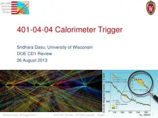
ATLAS L1 Calorimeter Trigger Upgrade - Uli Schäfer, MZ -. The ATLAS L1Calo collaboration Argonne, Birmingham, Cambridge, Heidelberg, Mainz, MSU, QMUL, RAL, Stockholm. Outline. Current L1 Calorimeter Trigger Phase 1 Pre-Processor upgrade Digital processors / topological trigger

E N D
ATLAS L1 Calorimeter Trigger Upgrade- Uli Schäfer, MZ - The ATLAS L1Calo collaboration Argonne, Birmingham, Cambridge, Heidelberg, Mainz, MSU, QMUL, RAL, Stockholm
Outline • Current L1 Calorimeter Trigger • Phase 1 • Pre-Processor upgrade • Digital processors / topological trigger • Towards Phase 2
ATLAS Trigger / current L1Calo L1 Jet/Energy module µ calo CTP
Current L1Calo • Analog signal chain on- and off-detector • Mixed-signalPre-Processor with discrete analog and ASIC-based digital circuitry : digital filtering / gain control / bunch crossing identification • Digital processing: • Sliding windows algorithms for jet and em cluster detection on processor modules atgranularity ≥ .1×.1 (η×φ) • Data consolidation by thresholding and counting objects • Data transmission on parallel backplane to mergers • Global results determined by summation trees on daisy-chained merger modules • Final results of electromagnetic and hadronic object count (at given thresholds), and total and missing transverse energy reported to Central Trigger Processor • Topological information (Regions of Interest – ROIs – basically energy sumsper window) sent to 2nd level triggeronly for all level-1 accepted events
L1Calo upgrade • Due to expected increase in pile-up of events at rising luminosities, the current algorithms will be degraded • Trying to improve L1Calo algorithms in two phases. • Phase-1: • Improve digital signal processing on Pre-Processor • Add topological processing with limited hardware modifications / additions • Phase-2: improve granularity of L1Calo algorithms in η, φ, and depth. Replacement of L1Calo. • NB : • I am presenting here a snapshot of current thinking only • The upgrade steps are related to, but not strictly dependent on the LHC machine upgrade steps • L1Calo will attempt to stage the installation of new hardware, i.e. there are likely to be sub-phases • Phase-1 upgrade is mainly internal to L1Calo, no strict need for modifications of external interfaces • Phase-2 is dependent on calorimeter readout electronics upgrade • Don‘t expect me to present a timeline…
L1Calo upgrade simulation • Simulations of trigger algorithms at high luminosity / high pileup scenarios are being pursued within L1Calo community: Cambridge, Mainz, MSU, QMUL… • Initial results indicate need for considerable improvement on L1Calo algorithms • Just an example… SUSY trigger… • L1 trigger rates for 2-jet events at 1034 cm-2s-1 • Require Etmiss > 30 GeV • Threshold energy of 2nd leading jet • … and now cut on topology:Δφ(jet1,jet2) Benefit from use of topological information
New MCM • We would like to develop a pin-, size- and latency-compatible substitute for the MCM based on today's components: • AD9218 -- dual FADC, 105MHz, 10bit • Xilinx Spartan-6 (SC6SLX45) FPGA in the CSG324 (15x15) package • Functionality of ASIC, PHOS4 and LVDS Serialisers inside FPGA Modern reconfigurable device will allow us to adjust and to add new pre-processing algorithms (event-by-event pedestal subtraction, more sophisticated BCID algorithms, etc.) for higher luminosity expected after the LHC Upgrade
LVDS Serializers • 480Mb/s serialisers for LVDS are implemented using Spartan-6 output serialiser blocks (OSERDES2). Eye-diagram shows a good signal quality:
PprASIC • PprASIC (including serializers) verilog code is adopted and synthesized for the Spartan-6 FGPA. • Estimated power consumption: • FPGA: ~200 mW • ADC: ~275 mW per channel at 105MHz; ~1W on module
nMCM PCB Layout • 10 layers design • Aim is to keep production technology as ''standard-and-simple'' as possible
and the digital processors : Topology • So far topology of identified objects not propagated through 1st level trigger real-time data path for bandwidth reason • Increase RTDP bandwidth and send (almost) full ROI information to a single processor stage where topology cuts are applied and double counting is suppressed by jet/electron/... matching: • Increase backplane bandwidth of existent processor modules 4-fold (40Mb/s160Mb/s) with modification to FPGA code only • Replace the merger modules by “CMM++” modules • Single FPGA processor • 16*25bit*160Mb/s (=64Gb/s) parallel input capability • Possibly up to ~400Gb/s optical I/O • Backward compatible to current merger modules so as to allow for staged installation scenario • Daisy-chain CMM++s electrically or optically similar to current scheme • Star-couple all CMM++s into topological processor for maximum performance
New merger module: CMM++ VME -- VME CPLD Legacy DAQ, ROI readout (Glink) SNAP12 Topologicalprocessor links: 12-fiber bundles, 6.4/10 Gbit/s/fiber Virtex 6 HX565T LVDS merger links SNAP12 SNAP12 SNAP12 Backplane data from JEM/CPM modules (160 MHz) Legacy LVDS outputs to CTP SNAP12 SNAP12 9U × 40 cm
L1Calo Phase-1 • Daisy chained • Combination of low-latency LVDS + high bandwidth optolinks CMM++ Full system w.topo processor single crate
Demonstrators / Prototypes so far… • Work on CMM++ prototype has started recently. Currently at specifications stage. VHDL system modelling started at MSU. • “GOLD” demonstrator (not just) for a topological processor currently being developed in Mainz Latency data replication schemesDensity processing power, connectivity • Mainz-built “BLT” backplane and link tester successfully verified 160Mb/s data reception on the processor backplane. Equipped with SNAP12 opto-link interface and LHC bunch clock jitter cleaning hardware required on CMM++
GOLD concept «data concentrator» scheme:many in – few out • Advanced TCA form factor • Limited connectivity on front panel • Input links via optical connectors in zone 3 • 12-channel 10Gb/s opto modules on daughter card • Electrical connectivity up to 10Gb/s in zone 2 • Power budget ~400W • RTM • front • Z3 • back • Z2 • ATCA
GOLD floor plan • Z3 • 5 * XC6VLX FPGAs(Processor L, merger M) up to 36 links each • Two pairs of XC6VHX FPGAs (H) 72 links • 5+ 12-channel optos on daughter • Clock generation • 144 multigigabit links in zone 2 (equiv. 22300 bit / BC) • L • L • Opto • M • L • L • H • H • Z2 • 890Gb/s • total • H • H • Z1
Optics & modulestatus • Module currently being hand-routed (~ 400 differential pairs per FPGA) • Daughter modules yet to be designed upto 72 fibres per connector (MPO/MTP)
eventually … Phase 2 ! « Once the calorimeter readout is replaced … in 20xx … » • High granularity trigger data provided on optical links • New sliding windows processor with optical interfaces only • Synchronous low-latency L0 plus asynchronous L1
Summary • Need for substantial improvement of trigger algorithms indicated by initial simulation results • Timeline fortrigger upgrade not strictlydependent on LHC upgrade phases • Work hasstarted on conceptualdesignsanddemonstratorsfor upgrade phases 1 and 2 • Likelyhavingtowork on phase-1 and phase-2 hardwareprojectsconcurrently • Benefitfromsimilarrequirements on phase 1 and 2