Download
1 / 52
520 likes | 737 Views
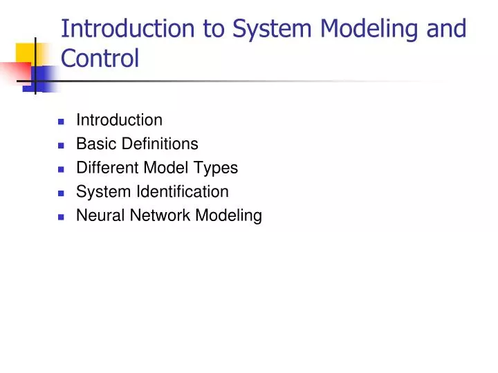
Introduction to System Modeling and Control. Introduction Basic Definitions Different Model Types System Identification Neural Network Modeling. Mathematical Modeling (MM). A mathematical model represent a physical system in terms of mathematical equations

E N D
Introduction to System Modeling and Control • Introduction • Basic Definitions • Different Model Types • System Identification • Neural Network Modeling
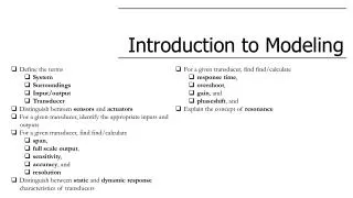
Mathematical Modeling (MM) • A mathematical modelrepresent a physical system in terms of mathematical equations • It is derived based on physical laws (e.g.,Newton’s law, Hooke’s, circuit laws, etc.) in combination with experimental data. • It quantifies the essential features and behavior of a physical system or process. • It may be used for prediction, design modification and control.
Numerical Solution Theory Solution Data Data Engineering System Math. Model Model Reduction Control Design Graphical Visualization/Animation Engineering Modeling Process • Example: Automobile • Engine Design and Control • Heat & Vibration Analysis • Structural Analysis
Definition of System • System: An aggregation or assemblage of things so combined by man or nature to form an integral and complex whole. • From engineering point of view, a system is defined as an interconnection of many components or functional units act together to perform a certain objective, e.g., automobile, machine tool, robot, aircraft, etc.
System Variables Every system is associated with 3 variables: • Input variables (u) originate outside the system and are not affected by what happens in the system • State variables (x) constitute a minimum set of system variables necessary to describe completely the state of the system at any given time. • Output variables (y) are a subset or a functional combination of state variables, which one is interested to monitor or regulate. y u System x
Mathematical Model Types discrete-event distributed Lumped-parameter Most General Input-Output Model Linear-Time invariant (LTI) LTI Input-Output Model Discrete-time model: Transfer Function Model
u x x fs fs M M fd fd Example: Accelerometer (Text 6.6.1) Consider the mass-spring-damper (may be used as accelerometer or seismograph) system shown below: Free-Body-Diagram fs(y): position dependent spring force, y=u-x fd(y): velocity dependent spring force Newton’s 2nd law Linearizaed model:
Example II: Delay Feedback Consider the digital system shown below: Input-Output Eq.: Equivalent to an integrator:
U G Y Transfer Function Transfer Function is the algebraic input-output relationship of a linear time-invariant system in the s (or z) domain Example: Accelerometer System Example: Digital Integrator Forward shift
Comments on TF • Transfer function is a property of the system independent from input-output signal • It is an algebraic representation of differential equations • Systems from different disciplines (e.g., mechanical and electrical) may have the same transfer function
Acceleromter Transfer Function • Accelerometer Model: • Transfer Function: Y/A=1/(s2+2ns+n2) • n=(k/m)1/2, =b/2n • Natural Frequency n, damping factor • Model can be used to evaluate the sensitivity of the accelerometer • Impulse Response • Frequency Response
Frequency Response /n
Mixed Systems • Most systems in mechatronics are of the mixed type, e.g., electromechanical, hydromechanical, etc • Each subsystem within a mixed system can be modeled as single discipline system first • Power transformation among various subsystems are used to integrate them into the entire system • Overall mathematical model may be assembled into a system of equations, or a transfer function
Ra La B ia dc u J Electro-Mechanical Example Input: voltage u Output: Angular velocity Elecrical Subsystem (loop method): Mechanical Subsystem
Ra La B ia dc u Electro-Mechanical Example Power Transformation: Torque-Current: Voltage-Speed: where Kt: torque constant, Kb: velocity constant For an ideal motor Combing previous equations results in the following mathematical model:
Brushless D.C. Motor • A brushless PMSM has a wound stator, a PM rotor assembly and a position sensor. • The combination of inner PM rotor and outer windings offers the advantages of • low rotor inertia • efficient heat dissipation, and • reduction of the motor size.
dq-Coordinates b q d e a e=p + 0 c offset Electrical angle Number of poles/2
Mathematical Model Where p=number of poles/2, Ke=back emf constant
System identification Experimental determination of system model. There are two methods of system identification: • Parametric Identification: The input-output model coefficients are estimated to “fit” the input-output data. • Frequency-Domain (non-parametric): The Bode diagram [G(j) vs. in log-log scale] is estimated directly form the input-output data. The input can either be a sweeping sinusoidal or random signal.
Ra La B ia Kt u 12 10 u 8 t 6 Amplitude 4 T 2 0 0 0.1 0.2 0.3 0.4 0.5 Time (secs) Electro-Mechanical Example Transfer Function, La=0: k=10, T=0.1
Comments on First Order Identification Graphical method is • difficult to optimize with noisy data and multiple data sets • only applicable to low order systems • difficult to automate
Least Squares Estimation • Given a linear system with uniformly sampled input output data, (u(k),y(k)), then • Least squares curve-fitting technique may be used to estimate the coefficients of the above model called ARMA (Auto Regressive Moving Average) model.
Method I (Sweeping Sinusoidal): f Ao Ai system t>>0 Method II (Random Input): system Transfer function is determined by analyzing the spectrum of the input and output Frequency-Domain Identification
System Models high order low order
Nonlinear System Modeling& Control Neural Network Approach
Introduction • Real world nonlinear systems often difficult to characterize by first principle modeling • First principle models are oftensuitable for control design • Modeling often accomplished with input-output maps of experimental data from the system • Neural networks provide a powerful tool for data-driven modeling of nonlinear systems
What is a Neural Network? • Artificial Neural Networks (ANN) are massively parallel computational machines (program or hardware) patterned after biological neural nets. • ANN’s are used in a wide array of applications requiring reasoning/information processing including • pattern recognition/classification • monitoring/diagnostics • system identification & control • forecasting • optimization
Advantages and Disadvantages of ANN’s • Advantages: • Learning from • Parallel architecture • Adaptability • Fault tolerance and redundancy • Disadvantages: • Hard to design • Unpredictable behavior • Slow Training • “Curse” of dimensionality
Biological Neural Nets • A neuron is a building block of biological networks • A single cell neuron consists of the cell body (soma), dendrites, and axon. • The dendrites receive signals from axons of other neurons. • The pathway between neurons is synapse with variable strength
Artificial Neural Networks • They are used to learn a given input-output relationship from input-output data (exemplars). • The neural network type depends primarily on its activation function • Most popular ANNs: • Sigmoidal Multilayer Networks • Radial basis function • NLPN (Sadegh et al 1998,2010)
x1 y x2 weights activation function Multilayer Perceptron • MLP is used to learn, store, and produce input output relationships • The activation function (x) is a suitable nonlinear function: • Sigmidal: (x)=tanh(x) • Gaussian: (x)=e-x2 • Triangualr (to be described later)
y x W0 Wp Multilayer Netwoks Wk,ij: Weight from node i in layer k-1 to node j in layer k
Universal Approximation Theorem (UAT) Comments: • The UAT does not say how large the network should be • Optimal design and training may be difficult A single hidden layer perceptron network with a sufficiently large number of neurons can approximate any continuous function arbitrarily close.
Training • Objective: Given a set of training input-output data (x,yt) FIND the network weights that minimize the expected error • Steepest Descent Method: Adjust weights in the direction of steepest descent of L to make dL as negative as possible.
Neural Network Approximation of NARMA Model y u[k-1] y[k-m] Question: Is an arbitrary neural network model consistent with a physical system (i.e., one that has an internal realization)?
State-Space Model u y system States: x1,…,xn
A Class of Observable State Space Realizable Models • Consider the input-output model: • When does the input-output model have a state-space realization?
Comments on State Realization of Input-Output Model • A Generic input-Output Model does not necessarily have a state-space realization (Sadegh 2001, IEEE Trans. On Auto. Control) • There are necessary and sufficient conditions for realizability • Once these conditions are satisfied the state-space model may be symbolically or computationally constructed • A general class of input-Output Models may be constructed that is guaranteed to admit a state-space realization
INTRODUCTION APPLICATIONS: • Robotics • Manufacturing • Automobile industry • Hydraulics EXAMPLE: EHPV control (electro-hydraulic poppet valve) • Highly nonlinear • Time varying characteristics • Control schemes needed to open two or more valves simultaneously
Motivation • The valve opening is controlled by means of the solenoid input current • The standard approach is to calibrate of the current-opening relationship for each valve • Manual calibration is time consuming and inefficient
Research Goals • Precisely control the conductivity of each valve using a nominal input-output relationship. • Auto-calibrate the input-output relationship • Use the auto-calibration for precise control without requiring the exact input-output relationship
INTRODUCTION EXAMPLE: • Several EHPV’s were used to control the hydraulic piston • Each EHPV is supplied with its own learning controller • Learning Controller employs a Neural Network (NLPN) in the feedback • Satisfactory results for single EHPV used for pressure control
Control Design • Nonlinear system (‘lifted’ to a square system) • Feedback Control Law • is the neural network output • The neural network controller is directly trained based on the time history of the tracking error