Download
1 / 16
170 likes | 329 Views
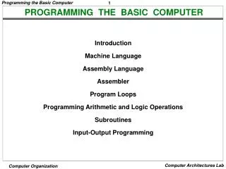
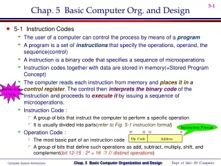
Chap. 6 Programming the Basic Computer. 6-1 Introduction Translate user-oriented symbolic program (alphanumeric character set) into binary programs recognized by the hardware 25 Instruction Set of the basic computer Memory Reference Instruction Register Reference Instruction

E N D
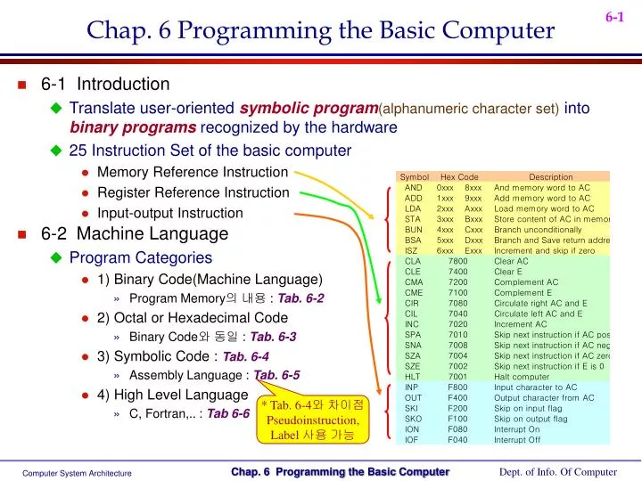
Chap. 6 Programming the Basic Computer • 6-1 Introduction • Translate user-oriented symbolic program(alphanumeric character set) into binary programs recognized by the hardware • 25 Instruction Set of the basic computer • Memory Reference Instruction • Register Reference Instruction • Input-output Instruction • 6-2 Machine Language • Program Categories • 1) Binary Code(Machine Language) • Program Memory의 내용 : Tab. 6-2 • 2) Octal or Hexadecimal Code • Binary Code와 동일 : Tab. 6-3 • 3) Symbolic Code : Tab. 6-4 • Assembly Language : Tab. 6-5 • 4) High Level Language • C, Fortran,.. : Tab 6-6 * Tab. 6-4와 차이점 Pseudoinstruction, Label 사용 가능
Label Instruction Comment • 6-3 Assembly Language • The rules for writing assembly language program • Documented and published in manuals(from the computer manufacturer) • Rules of the Assembly Language • Each line of an assembly language program is arranged in three columns • 1) Label field : empty or symbolic address • 2) Instruction field : machine instruction or pseudoinstruction • 3) Comment field : empty or comment • Symbolic Address(Label field) • One, two, or three, but not more than three alphanumeric characters • The first character must be a letter; the next two may be letters or numerals • A symbolic address is terminated by a comma(recognized as a label by the assembler) • Instruction Field • 1) A memory-reference instruction(MRI) • Ex) ADD OPR(direct address MRI), ADD PTR I(indirect address MRI) • 2) A register-reference or input-output instruction(non-MRI) • Ex) CLA(register-reference), INP(input-output) • 3) A pseudoinstruction with(ORGN) or without(END) an operand : Tab. 6-7 • Pseudoinstruction 은 Machine Instruction이 아니고 Assembler에게 필요한 정보만 제공 Field
Comment field • Comment filed must be preceded by a slash(recognized by assembler as comment) • An Example Program : Tab. 6-8 • 83 - ( - 23 ) = 83 + ( 2’s Complement of -23) = 83 + 23 • Translation to Binary : Tab. 6-9 • Assembler = the translation of the symbolic(= assembly) program into binary • Address Symbol Table = Hexadecimal address of symbolic address • MIN = 106, SUB = 107, DIF = 108 • Two Pass Assembler : in next Sec. 6-4 • 1) 1st scan pass : generate user defined address symbol table • 2) 2nd scan pass : binary translation • 6-4 The Assembler • Source Program Object Code Binary Code 교과서에서는 같은 의미로 사용됨 Ex) LDA SUB 1) SUB = 107 2) 2107 Assembler (Compiler) Linker asm a96 a51 c(cpp) for pas obj bin exe com hex Library 또는 외부 함수를 사용하여 Relocation
Representation of Symbolic Program in Memory : Tab. 6-11 • Line of Code : PL3, LDA SUB I (Carriage return) • The assembler recognizes a CR code as the end of a line of code • Two Pass Assembler • 1) 1st pass : Generate user- defined address symbol table • Flowchart of first pass : Fig. 6-1 • Address Symbol Table for Program in Tab. 6-8 : Tab. 6-12 Fig. 6-1 Flowchart for first pass of assembler
1 2 3 4 5 6 …. … 15 16 I Opcode Address • 2) 2nd pass : Binary translation • 다음의 4 개의 Table을 참고하여 Instruction Format에 의한 Binary Code 형성 (Pseudoinstruction Table, MRI Table, Non-MRI Table, Address Symbol Table) • Flowchart of second pass : Fig. 6-2 • Binary Code translation 예제 : Tab. 6-9의 Content • Error Diagnostics • Check for possible errors in the symbolic program • Ex) Invalid Machine Code Error Tab. 6-9 에서의 Contents를 결정 이 경우는 Hand Assemble Error Pseudoinstruction, MRI, non-MRI 에 속하지 않음 Fig. 6-2 Flowchart for second pass of assembler
6-5 Program Loops • Program Loops • A sequence of instructions that are executed many times • Example of program loop • Sum of 100 integer numbers • Fortran • Symbolic Program : Tab 6-13 • Address 150 부터 100 개의 Data를 더하기 Tab. 6-13 Symbolic Program to Add 100 numbers DIMENSION A(100) INTEGER SUM, A SUM = 0 DO 3 J = 1, 100 3 SUM = SUM + A(J) Data
P = 0 0 0 0 0 0 0 0 + 0 0 0 0 1 1 1 1 P = 0 0 0 0 1 1 1 1 + 0 0 0 1 1 1 1 0 P = 0 0 1 0 1 1 0 1 + 0 0 0 0 0 0 0 0 P = 0 0 1 0 1 1 0 1 + 0 1 1 1 1 0 0 0 P = 1 0 1 0 0 1 0 1 X = 1 1 1 1 Y = 1 0 1 1 1 1 1 1 1 1 1 1 0 0 0 0 1 1 1 1 1 0 1 0 0 1 0 1 • 6-6 Programming Arithmetic & Logic Operations • Hardware implementation • Operations are implemented in a computer with one machine instruction • Ex) ADD, SUB : 그러나 자리수가 늘어나면 Software subroutine 처리 • Software implementation • Operations are implemented by a set of instruction(Subroutine) • Ex) MUL, DIV : 그러나 이와 같은 명령어를 갖는 CPU도 있음 • Multiplication Program • Positive Number Multiplication • X = multiplicand Y = multiplier P = Partial Product Sum • Y 를 AC 에 저장한 후 E 로 Circular Right • E = 1 : P에 1111을 더함 • E = 0 : 더하지 않음 Algorithm Fig. 6-3
Fig. 6-3 flowchart for Multiplication Program Tab. 6-14 Program to Multiply Two Positive numbers
31 16 15 0 AH AL BH BL CH CL • Double Precision Addition : 32 bits • 하위 AL + BL먼저 수행하여 E 를 상위에 반영(AH + BH + E) • Logic Operations • Logic Operation 중에서 OR명령이 없다(Tab. 6-1) • 추가 하려면 더 길은 Instruction Format 필요 • 해결 방법 : DeMorgan’s theorem +
E E E 0 0 1 0 0 1 E 0 0 • Shift Operations • Logical Shift : Zero must added to the extreme position • Shift Right • Shift Left • Arithmetic Shift Right • Positive ( + = 0 ) • Negative ( - = 1 ) CLE CIR CLE CIL • 6-7 Subroutines • Subroutine • A set of common instruction that can be used in a program many times • In basic computer, the link between the main program and a subroutine is the BSA instruction(Branch and Save return Address) • Subroutine example : Tab. 6-16
Subroutine CALL hear Ex) 1234 - CIL 4 회 = 2340 - Mask : AND FFF0 - 결과 = 2340 X = 102 Y = 105 Tab. 6-16 Program to Demonstrate the use of Subroutines
Subroutine Parameters & Data Linkage • Parameter(or Argument) Passing • When a subroutine is called, the main program must transfer the data • 2 가지 Parameter Passing 방법 • 1) Data transfer through the Accumulator • Used for only single input and single output parameter • 2) Data transfer through the Memory • 여러 개의 Operand 전달 가능 • Operand are often placed in memory locations following the CALL • 2 개의 Parameter Passing 예 : Tab. 6-17 • First Operand and Result : Accumulator • Second Operand : Inserted in location following the BSA • BSA후에 2개 Operand 예 : Tab. 6-18 • BSA 후에 2개의 Operand 사용 • Block 전송 Source 와 Destination Address로 사용 Tab. 6-17 Program to Demonstrate Parameter Linkage Call 후에 Return Address를 이용 * OR Subroutine First Operand : X = 7B95 Second Operand : BSA후 = 3AF6
Tab. 6-18 Subroutine to Move a Block of Data 2 개의 Operand * Block Move Subroutine 메모리 200 번지 부터 16개의 데이터를 메모리 300 번지로 이동
1st Char 2nd Char • 6-8 Input-Output Programming • One-character I/O • Programmed I/O 방식 • Two-character I/O • Two character Packing Tab. 6-19 Program to input and output One character Tab. 6-20 Subroutine to input and pack Two character 15 8 7 0 1st Char 1st Char
Store Input Character in Buffer • Compare Two Word Tab. 6-21 Program to store input character in buffer Tab. 6-22 Program to compare Two word
Interrupt Program • Interrupt Condition • Interrupt F/F R = 1 when IEN = 1 and [FGIorFGO = 1] • Save return address at 0000 • Jump to 0001 (Interrupt Start) • Interrupt Service Routine(ISR) • 1) Save Register (AC, E) • 2) Check Input or Output Flag • 3) Input or Output Service Routine • 4) Restore Register (AC, E) • 5) Interrupt Enable (ION) • 6) Return to the running program Interrupt Here Modified Fetch Cycle 과 Reset 시에 IEN = 0 이 된다 (p. 158, Fig. 5-15)