Download
1 / 27
350 likes | 655 Views
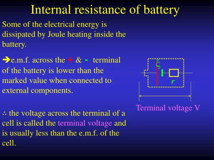
ξ. r. Internal resistance of battery. e.m.f. across the + & - terminal of the battery is lower than the marked value when connected to external components. Some of the electrical energy is dissipated by Joule heating inside the battery. Terminal voltage V.

E N D
ξ r Internal resistance of battery e.m.f. across the + &- terminal of the battery is lower than the marked value when connected to external components. Some of the electrical energy is dissipated by Joule heating inside the battery. Terminal voltage V ∴ the voltage across the terminal of a cell is called the terminal voltage and is usually less than the e.m.f. of the cell.
ξ I I r => ξ = R + r I => R = ξ - r V I Finding the internal resistance of the battery R ξ= V + Ir =IR + I r The current I through the circuit is varied by a resistance box which has known value of resistance R. ∴ by plotting a graph of R against 1 / I, a straight line can be obtained. The slope of the graph is ξ and the intercept on the y-axis is the internal resistance r.
In series Combination of Resistors All the resistors carry same current I V = V1 + V2 + V3 = I R1 + I R2 + I R3 = I ( R1 + R2 + R3 ) ∴ R = R1 + R2 + R3
Combination of resistors 2. In parallel The p.d. V across each resistors is the same., but the current branches into I1, I2 and I3.
Power and heating effect The charge pass through the resistor: The electrical energy converted into other form of energy in Δt: ∴ Power of the resistor:
Example 5 A light bulb labelled 12 V 10W is connected across a 12 V cell with internal resistance 5Ω. Find the power output. ∵ the cell has internal resistance, the p.d. across the light bulb ≠12 V. But the resistance of the bulb is fixed. The total resistance of the circuit is 5Ω + 14.4 Ω = 19.4 Ω The current flow through the circuit and the bulb is = 12 V / 19.4 Ω = 0.619 A
Classwork 1 A student connect a toy motor labelled 9 V 50 W across a 9 V battery with internal resistance 10 Ω. Find the power output by the toy motor. The total resistance of the circuit is 1.62Ω + 10 Ω = 11.62 Ω The current flow through the circuit and the toy motor is = 9 V /11.62 Ω = 0.775 A
Power output and Resistance The current flow through the above circuit: Power output through R: Max power occurs when R = r
Efficiency of Electric Circuit In general the power of the circuit. When max. power occurs, R = r, the efficiency is:
Example 6 A 1.5 V cell has an internal resistance of 2 Ω. Find the condition for a.) Max. Power. b.) Max. Efficiency. a.) Max. Power consumption occur when the cell is short circuit. b.) Max. useful power output occur when R = r i.e. external resistance = 2Ω
Classwork2 A 9 V cell has an internal resistance of 5 Ω. Find the power out put for a.) Max. Power. b.) Max. Efficiency. a.) Max. Power consumption occur when the cell is short circuit. b.) Max. useful power output occur when R = r i.e. external resistance = 5Ω
Power transmission In power transmission, the voltage across the power cable is VL – V’L. or ILR, where L is the current through the cable. The power loss by the cable is ∵ Power transfer to the user equal to the power generate, it usually remains constant
Typical Example ---- Combination of 2 cells ξ r1 - + ξ r2 Since any charge + or – cannot climb through the energy barrier set by the other cell, NO current flow through the cells.
14V 5Ω 20Ω 12V 15Ω Example 6 A 12V battery of internal resistance 15 Ω is recharged by a 14 V d.c. supply with internal resistance 5Ω via a 20 Ω. Find the current through the battery. Net e.m.f. = 14 V – 12 V = 2 V Total resistance = 15 + 5 + 20 = 40Ω Current = 2 V / 40 Ω = 0.05 = 50 mA
9V 10Ω 50Ω 1.5V 5Ω Classwork3 A student uses a 9V battery of internal resistance 10 Ω to charged a 1.5 V ‘AA’battery with internal resistance 5Ω via a 50 Ω resistor. Find the current through the battery. Net e.m.f. = 9 V – 1.5 V = 7.5 V Total resistance = 10 + 5 + 50 = 65Ω Current = 7.5 V / 65 Ω = 0.115 A
ξ I1 r1 ξ I2 r2 I R This is known as Kirchoff’s 1st law of current 2 parallel cell connected to a resistor The terminal voltage of the cells are the same and equal to the voltage across R ξ = I1 r1 + I R ξ = I2 r2 + I R I1 + I2 = I
Example 6 The light bulb in the diagram shown below has a resistance of 6 Ω. Find the power output. 1.5 V I1 2Ω 1.5 V I2 4Ω I 6Ω 1.5 V = I × 6Ω + I1 × 2Ω --- ( 1 ) 1.5 V = I × 6Ω + I2 × 4Ω --- ( 2 ) I = I1 + I2 --- ( 3 ) 1.5 V = (I1 + I2 ) × 6Ω + I1 × 2Ω 1.5 V = (I1 + I2 ) × 6Ω + I2 × 4Ω Solve, I1 = 0.06818 AandI2 = 0.136 A i.e. I = 0.06818 + 0.136 = 0.2042 A ∴ Power output of the bulb = 0.20422 × 6 = 0.25 W
Classwork 4 The light bulb in the diagram shown below has a resistance of 10 Ω. Find the power output. I1 1.5 V 5Ω 1.5 V I2 2Ω I 10Ω 1.5 V = I × 10Ω + I1 × 5Ω --- ( 1 ) 1.5 V = I × 10Ω + I2 × 2Ω --- ( 2 ) ( 1 ) × 2, ( 2 ) × 5 I = 0.13125 A ∴ Power output of the bulb = 0.131252 × 10 = 0.17226 W
I-V characteristics of junction diode ( semiconductor diode ) I / mA 20 mA VD / V 0.8 V 0.8 V 2.2 V R I ξ= 3V A diode allow current flow in 1 direction only. However, the voltage across the diode must reach a certain value to enable the charge carriers to flow. For the diode to operate, I ≧20 mA, the largest I
For a diode to operate safely, prevent it burn out, a maximum current must be noticed. This current is limited by the power rating of the diode.Assume a diode has a maximum rating of 0.08 W, the smallest R is given by: 0.8 V 2.2 V R I ξ= 3V For the diode to operate safely, ∴ the diode can be operated with a resistor of 22Ω≦R ≦110 Ω
Classwork 5 The I-V characteristic of a diode is shown below. The diode is operated with a resistor R. Given that the maximum power rating of the diode is 1 W. Calculate the maximum and minimum value of the resistor. I / mA 50 mA VD / V 1.2 V 1.2 V 7.8 V R I ξ= 9V Rmax = 156 Ω Rmin = 9.36 Ω
Thermionic diode 熱放電二極管 I / mA 2 mA VD / V 4 V VD 12V- VD - - R I ξ= 12V A thermionic diode is a evacuated glass tube with a heated cathode. Electrons is excited in the cathode and ‘jump’ to the anode inside the glass tube. If a diode is saturated at I = 2 mA, the number electrons reaches a maximum value and nor more electrons can flow inside the glass tube.
I / mA 2 mA VD / V 4 V VD 12V- VD - - R I ξ= 12V If the diode is just saturated, the voltage across the diode VD is 4 V and the current I = 2 mA. 12 V = VD + I R = VD + 2 mA × R VD = 12 V - 2 mA × R Since I must be larger than 2 mA, the resistor must be smaller than a certain value. VD > 4V 12V – 2 mA × R > 4V ∴R < 4000 Ω
Bridge circuit 1Ω 1Ω 1Ω 1Ω No current ∵ same p.d. 10Ω 10Ω 10Ω 10Ω 4 V
P Q I1 I2 R S VP= VR I1 P = I2 R VQ= VS I1 Q = I2 S
Classwork 6 The ammeter in the diagram below shows no reading. Calculate the resistance of the unknown resistor P P 25Ω 64Ω 40Ω P = 40 Ω