Download
1 / 33
580 likes | 1.19k Views
I/O Ports in AVR Chapter 4. The AVR microcontroller and embedded systems using assembly and c. Topics. AVR pin out The structure of I/O pins I/O programming Bit manipulating. AVR IO Panel Simulation in AVR Studio 4.

E N D
I/O Ports in AVRChapter 4 The AVR microcontroller and embedded systems using assembly and c
Topics • AVR pin out • The structure of I/O pins • I/O programming • Bit manipulating
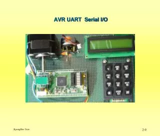
AVR IO Panel Simulationin AVR Studio 4 • The IO Panel Simulation Installer is in folder \Lecture Notes\AVRStudio4\Installer • Refer to AVRstudio IO simulation.pdf in folder \Lecture Notes\E-Books and Reference for tutorial on how simulate IO in AVR Studio 4. • Or follow the sequence of next instructions • WinAVR-20100110-install.exe in folder \Lecture Notes\AVRStudio4\Installer\WinAVR-20100110must installed if not done yet. • Then Execute build.bat in folder \Lecture Notes\AVRStudio4\Installer\IO panel Simulator\LCDTest • The drag icon in folder \Lecture Notes\AVRStudio4\Installer\IO panel Simulator\hapsim217 to the taskbar.
Executing IO Panel Simulation • Everytime you need to execute IO Panel Simulation: • AVR Studio 4.18 must be executed first. • The Execute • If executes successfully, the following window will open. • Otherwise check if steps in previous page has been taken correctly. Redo if necessary.
Confirming If HAPSIM Is Hook To AVR Studio • Press the Option menu and you will find that AVRStudioHook sub-menu is checked as shown below. • By default LCD – HD44780U panel window is opened. You may close this panel and reopen again.
Selecting IO Panel to be virtually connected to ATmega32 microcontroller • Press the icon and scroll down to select ATmega32 as shown below.
Opening An I/O panel • Press the icon and the following New window will open over the HAPSIM window. • Four I/O panel name will be displayed. • If scroll down you will find more I/O panel name as shown below. • Select the LEDs I/O panel and the LEDs panel will be opened asshown in the bottom right of this page.
Setting Vitual Connection of I/O Panel to the AVRStudio • On the Option Menu Select LED Settings and the LED Settings windowwill opened. • You can change LED Name, Color, virtual connection to the bit # of the port of the microcontroller. • The press OK
Testing the Virtual Connection of the LEDs Panel to AVRStudio Simulator • Open a Atmel AVR Assembler project for the ATmega32 microcontroller and write the program in the following page. • Build and Run the program. • Watch The LED panel at HIPSIM window • You will see that the program cause the LED panel displays a 8 bit binary count up.
Program to test LED panel .include "M32def.inc" .org 0 ldi r20,high(RAMEND) out sph,r20 ldi r20,low(RAMEND) out spl,r20 ldi r20,0xff;Set Port A as output out ddra,r20 ldi r20,0x0 ;r0 <-- 0 loop: inc r20 ;r0 <-- r0+1 out porta,r20 ;Port A<-R20 call delay1s ;delay rjmp loop delay1s: ldi r16,200 delay1s0: ldi r17,0xff delay1s1: dec r17 brne delay1s1 dec r16 brne delay1s0 ret
ATmega16/mega32 pinout +5 V +5 V +5 V • Vital Pins: • Power • VCC • Ground • Crystal • XTAL1 • XTAL2 • Reset • I/O pins • PORTA, PORTB, PORTC, and PORTD • Internal ADC pins • AREF, AGND, AVCC
Example 1 1 1 1 1 1 1 1 1 DDRA: 1 1 1 1 1 1 1 1 PORTA: • Write a program that makes all the pins of PORTA one. .INCLUDE “M32DEF.INC” LDI R20,0xFF ;R20 = 11111111 (binary) OUT PORTA,R20 ;PORTA = R20 OUT DDRA,R20 ;DDRA = R20
Example 2 • The following code will toggle all 8 bits of Port B forever with some time delay between “on” and “off” states: LDI R16,0xFF ;R16 = 0xFF = 0b11111111 OUT DDRB,R16 ;make Port B an output port (1111 1111) L1: LDI R16,0x55 ;R16 = 0x55 = 0b01010101 OUT PORTB,R16 ;put 0x55 on port B pins CALL DELAY LDI R16,0xAA ;R16 = 0xAA = 0b10101010 OUT PORTB,R16 ;put 0xAA on port B pins CALL DELAY RJMP L1
Example 3 1 1 1 1 1 1 1 1 DDRC: 0 0 0 0 0 1 1 0 PORTC: • A 7-segment is connected to PORTA. Display 1 on the 7-segment. ATmega32 0 5 1 .INCLUDE “M32DEF.INC” LDI R20,0x06 ;R20 = 00000110 (binary) OUT PORTC,R20 ;PORTC = R20 LDI R20,0xFF ;R20 = 11111111 (binary) OUT DDRC,R20 ;DDRC = R20 L1: RJMP L1 6 8 PORTC 2 4 3
Example 4 1 1 1 1 1 1 1 1 DDR: 0 1 0 0 1 1 1 1 PORTC: • A 7-segment is connected to PORTA. Display 3 on the 7-segment. ATmega32 0 5 1 .INCLUDE “M32DEF.INC” LDI R20,0x4F ;R20 = 01001111 (binary) OUT PORTC,R20 ;PORTC = R20 LDI R20,0xFF ;R20 = 11111111 (binary) OUT DDRC,R20 ;DDRC = R20 L1: RJMP L1 6 8 PORTC 2 4 3
Example 5: Input • The following code gets the data present at the pins of port C and sends it to port B indefinitely, after adding the value 5 to it: .INCLUDE "M32DEF.INC" LDI R16,0x00 ;R16 = 00000000 (binary) OUT DDRC,R16 ;make Port C an input port LDI R16,0xFF ;R16 = 11111111 (binary) OUT DDRB,R16 ;make Port B an output port(1 for Out) L2: IN R16,PINC ;read data from Port C and put in R16 LDI R17,5 ADD R16,R17 ;add 5 to it OUT PORTB,R16 ;send it to Port B RJMP L2 ;continue forever
The structure of I/O pins DDRx.n OUTPUT PORTx.n INPUT PINx.n
Example 6 • Write a program that continuously sends out to Port C the alternating values of 0x55 and 0xAA. .INCLUDE "M32DEF.INC" LDI R16,0xFF ;R16 = 11111111 (binary) OUT DDRC,R16 ;make Port C an output port L1: LDI R16,0x55 ;R16 = 0x55 OUT PORTC,R16 ;put 0x55 on Port C pins LDI R16,0xAA ;R16 = 0xAA OUT PORTC,R16 ;put 0xAA on Port C pins RJMP L1
Example 7 • Write a program that reads from port A and writes it to port B. .INCLUDE “M32DEF.INC” LDI R20,0x0 ;R20 = 00000000 (binary) OUT DDRA,R20 ;DDRA = R20 LDI R20,0xFF ;R20 = 11111111 (binary) OUT DDRB,R20 ;DDRB = R20 L1: IN R20,PINA ;R20 = PINA OUT PORTB,R20 ;PORTB = R20 RJMP L1
SBI and CBI instructions • SBI (Set Bit in IO register) • SBI ioReg, bit ;ioReg.bit = 1 • Examples: • SBI PORTD,0 ;PORTD.0 = 1 • SBI DDRC,5 ;DDRC.5 = 1 • CBI (Clear Bit in IO register) • CBI ioReg, bit ;ioReg.bit = 0 • Examples: • CBI PORTD,0 ;PORTD.0 = 0 • CBI DDRC,5 ;DDRC.5 = 0
Example • Write a program that toggles PORTA.4 continuously. .INCLUDE “M32DEF.INC” SBI DDRA,4 L1: SBI PORTA,4 CBI PORTA,4 RJMP L1
Example • An LED is connected to each pin of Port D. Write a program to turn on each LED from pin D0 to pin D7. Call a delay module before turning on the next LED. .INCLUDE "M32DEF.INC" LDI R20, 0xFF OUT DDRD, R20 ;make PORTD an output port SBI PORTD,0 ;set bit PD0 CALL DELAY ;delay before next one SBI PORTD,1 ;turn on PD1 CALL DELAY ;delay before next one SBI PORTD,2 ;turn on PD2 CALL DELAY SBI PORTD,3 CALL DELAY SBI PORTD,4 CALL DELAY SBI PORTD,5 CALL DELAY SBI PORTD,6 CALL DELAY SBI PORTD,7 CALL DELAY
SBIC and SBIS • SBIC (Skip if Bit in IO register Cleared) • SBIC ioReg, bit ; if (ioReg.bit = 0) skip next instruction • Example: SBIC PORTD,0 ;skip next instruction if PORTD.0=0 INC R20 LDI R19,0x23 • SBIS (Skip if Bit in IO register Set) • SBIS ioReg, bit ; if (ioReg.bit = 1) skip next instruction • Example: SBIS PORTD,0 ;skip next instruction if PORTD.0=1 INC R20 LDI R19,0x23
Example .INCLUDE "M32DEF.INC" CBI DDRB, 2 ;make PB2 an input SBI PORTB,2 LDI R16, 0xFF OUT DDRC, R16 ;make Port C an output port SBI DDRD, 3 ;make PD3 an output AGAIN: SBIS PINB, 2 ;Skip if Bit PB2 is HIGH RJMP AGAIN ;keep checking if LOW LDI R16, 0x45 OUT PORTC, R16 ;write 0x45 to port C SBI PORTD, 3 ;set bit PD3 (H-to-L) CBI PORTD, 3 ;clear bit PD3 HERE: RJMP HERE • Write a program to perform the following: • (a) Keep monitoring the PB2 bit until it becomes HIGH; • (b) When PB2 becomes HIGH, write value $45 to Port C, and also send a HIGH-to-LOW pulse to PD3.
Example .INCLUDE "M32DEF.INC" CBI DDRB,0 ;make PB0 an input SBI DDRB,7 ;make PB7 an output AGAIN: SBIC PINB,0 ;skip next if PB0 is clear RJMP OVER ;(JMP is OK too) CBI PORTB,7 RJMP AGAIN ;we can use JMP too OVER: SBI PORTB,7 RJMP AGAIN ;we can use JMP too • A switch is connected to pin PB0 and an LED to pin PB7. Write a program to get the status of SW and send it to the LED.