Download
1 / 12
130 likes | 416 Views
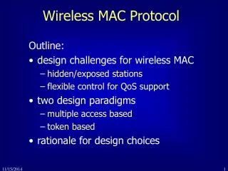
802.11 MAC Protocol. By Ervin Kulenica & Chien Pham. Introduction. Wireless telephony has been successful because it enables people to connect with each other regardless of location.

E N D
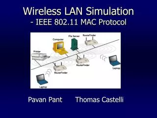
802.11 MAC Protocol By Ervin Kulenica & Chien Pham
Introduction • Wireless telephony has been successful because it enables people to connect with each other regardless of location. • This new technology targeted computer networking, and now the Internet connectivity is implemented successfully by wireless networking technology. • In 1997, the IEEE adopted the IEEE 802.11 standard which is used for wireless computer communication. The IEEE 802.11 defines two layers ,(PHY) which specifies the modulation scheme used and signaling characteristics for the transmission through radio frequencies. The second layer is the media access control (MAC). This layer determines how the medium is used. • In this project we will focus more on the MAC layer.
Theoretical background • 2.1 What is MAC? • The MAC is a set of rules to determine how to access the medium and data link components.The MAC rides on every transmission of user data into the air. It provides the core framing operations and the interaction with a wired network backbone. • The MAC layer supports two modes of operations,the point coordination function (PCF) and the second mode is the distributed coordination function (DCF). The PCF is built on top of the DCF, and is used only on infrastructure networks.
2.2 The distributed coordinated function. The DCF mode uses the carrier sense multiple access with collision avoidance (CSMA/CA) protocol. In this protocol, the user must sense the wireless medium first. If the medium is busy, random “backoff time” and tries again. There are two control packet that are exchanged before the transmission. (RTS) “ready to send” , which contains the source station address, the destination station address and the duration of the intended packet. Upon receiving the RTS, the destination it responds with a response control packet called “clear to send” (CTS) with the same information contained in it.
Project Goals In the past, having a wireless connection was a privilege. Users were more forgiving when the network failed. Today, their expectations are much higher. • We will address hidden node problem. • We will use java applet to have an animation solution of the problem. • Comparison of the three types of wireless network communication : a) Random communication between nodes without using RTS/CTS. b) Controlled communication using RTC/CTS control packets. c) Collision with RTS packets at the deaf node.
Implementation details • In the first applet, we’ll show how stations send packets to one anther randomly without using RTS/CTS control packets. One major problem that we will address is the hidden node problem. • Hidden nodes are nodes that are within the range of the receiver but not in the range of the sender. From the picture below, if node A is sending data to node B, node C is the hidden node with respect to node A. Figure 1 both A and C send packet to B(collision) In the second applet, we add RTS/CTS control packets before data are being sent. We’ll see from the applet that no data will be lost and the medium is used more efficiently.
Simplification and Design Assumptions • We made an assumption in the second applet that all the neighbor nodes remain silent while the transmission takes place. However, if the neighbor nodes of B and E misinterpreted the RTS/CTS packets then collisions can still occur. Figure 2 illustrates this situation.
If node B is transmitting data to node A, and node C is transmitting data to node D, then node E is known as the “deaf node”. If node E misinterprets the CTS and sends something to A, node A will not understand signal because packets from B and E have collided at A.
Analysis of the simulation • We expect three different results from the simulations. • We expect data loss due to constant packet collisions. • In the second scenario, data packets don’t get collided because they are protected by RTS/CTS packets. • Data packets collide with RTS packets at the deaf node. That is why it is very important to understand the dynamics of the system. In order to fully utilize the medium, we must fully understand the problems to develop an optimal solution.
Conclusions • We significantly improve our abilities in simplifying problems and understanding the core of wireless networking. • The project also helped us to improve our networking skills.
References • 1.Gast, Matthew S. Creating and Administering Wireless Networks, “802.11 Wireless Networks: The Definitive Guide”. O’Reilly & Associates, Inc. 2002. • 2.Larry L. Peterson & Bruce S. Davie. Computer Networks. A system approach. 3.http://www.ing.unipi.it/ew2002/proceedings/049.pdf 4.http://www.it.iitb.ac.in/it644/papers/802.11-perf-adhoc.pdf