Download
1 / 20
220 likes | 329 Views
Designing Packet Buffers for Router Linecards. Sundar Iyer, Ramana Kompella, Nick McKeown Reviewed by: Sarang Dharmapurikar. Background. Routers need to buffer packets during congestion Thumb rule : Buffer size should be RTT x R With RTT = 0.25s and R = 40 Gbps, Buffer size = 10 Gbits

E N D
Designing Packet Buffers for Router Linecards Sundar Iyer, Ramana Kompella, Nick McKeown Reviewed by: Sarang Dharmapurikar
Background • Routers need to buffer packets during congestion • Thumb rule : Buffer size should be RTT x R • With RTT = 0.25s and R = 40 Gbps, Buffer size = 10 Gbits • Can’t use SRAM, they are small and consume too much power • Only SDRAM provides the required density
Problems.. • SDRAM is slow, hence less memory bandwidth • Why not use a big data bus to get more memory bandwidth?
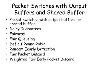
underutilized bandwidth Answer… 320 bytes Packet A Packet B Packet C
Parallel Memory Banks 320 bytes • However, packet departure order is not known • Scheduler might request for the packets which happen to be stored in the same bank • Hence one bank will be busy and others idle, degrading the throughput
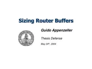
Alternative • Cache packets and write them in SDRAM as one word at a time for one queue • Likewise, read packets from DRAM, one word for a queue at a time, give out the necessary data and cache the rest 320 bytes A2 A1 B1 B2 C1 C2
Head SRAM buffer w ‘b’ bytes arrive in ‘b’ time slots all for the same queue 1 2 D(i,t) X(i,t) Scheduler ‘b’ bytes leave in b time slots Of these ‘b’ bytes, any byte can be from any queue i Q Objective : Put a bound on ‘w’
Additional b-1 bytes Under run starting b-1 bytes Lower Bound on the Head-SRAM size • Theorem 1: • w > (b-1)(2 + lnQ) • Example: • Let b = 3 • Q = 9 • Bytes required = (b-1) + (b-1) + under run
Lower bound on the Head-SRAM size • Proof of theorem 1: • First iteration : read one byte from each FIFO • Q/b FIFOs will be replenished with b bytes each • Q(1-1/b) FIFOs will have a deficit of D(i,Q) = 1 • Second iteration : read one byte from each of Q(1-1/b) FIFOs having D(i,Q) = 1 • Q(1-1/b)/b will be replenished with b bytes each • Q(1-1/b)2will have a deficit of D(i,Q) = 2 • Xth iteration : • Q(1-1/b)x FIFOs will have a deficit of D(i,Q) = x • Solve for Q(1-1/b)x = 1 • X > (b-1)lnQ • Hence, buffer rquirement is : w > (b-1)(2 + lnQ)
A Memory Management Algorithm • Objective: Give an Algorithm that is closer to this bound • Most Deficit Queue First (MDQF) • Service (replenish) the SRAM FIFO with most deficit first
Some Terminology… π1 1 2 π2 3 π3 4 π4 Q πQ
F(2, t-b) F(1) +b MDQF analysis • Lemma1 : F(1) < b[2+lnQ] j i i t -b t
F(3, t-b) +b MDQF Analysis F(2) p m m n n t -b t
MDQF Analysis F(i+1, t-b) F(i) +b • Theorem 2: For MDQF to guarantee that a requested byte is in SRAM, it is sufficient to hold b(3 + lnQ) bytes in each Head-FIFO t -b t
MMA that tolerates bounded pipeline delay • Pre-compute some of the memory requests to find out which queue under-runs • Critical Queue : A queue with more requests in the look ahead buffer than bytes to give • Earliest Critical Queue : A queue that turns critical the earliest
Most Deficit Queue First with Pipeline Delay (MDQFP) • Algorithm: • Replenish the earliest critical queue first • If no critical queues then replenish the one that will most likely become critical in the future • Lemma3: • Theorem 3: w = Fx(1) + b • Corollary 1 : x → Qb , w → 2b
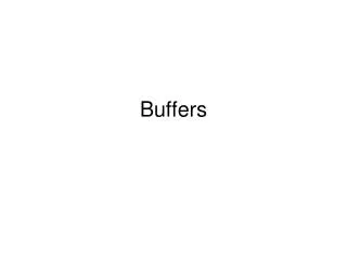
QFx(1), total SRAM Q = 1000, b=10 x, pipeline delay Tradeoff between SRAM size and pipeline delay
Dynamic SRAM allocation • So far all the queues had the same length which was static • SRAM can allocated dynamically to the queues depending on the requirement • further reduction in SRAM size • The amount of SRAM can be reduced to Q(b-1) for a Look ahead buffer of Q(b-1) + 1
Conclusions • High capacity and high throughput packet buffers are needed in any router line card • Packet buffers made out of only SRAMs are impractical, SDRAMs are used • SDRAM buffer memory used with SRAM cache memory can give the required throughput performance • Without any pipeline delay the SRAM requirement scales as QblnQ • With With tolerable delay of Qb time slots, the requirement scales as Qb