Download
1 / 13
140 likes | 433 Views
Tracker MRB Wire Bond Encapsulation from MCM to SSD. R.P. Johnson U.C. Santa Cruz. 1. Description of the Nonconformance.

E N D
TrackerMRBWire Bond Encapsulation from MCM to SSD R.P. Johnson U.C. Santa Cruz Tracker
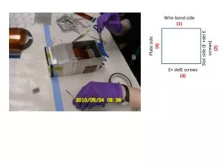
1. Description of the Nonconformance • A large fraction of the wire bonds connecting MCM to SSD Ladders broke loose from the SSDs on both tray sides during thermal cycling of the 4 heavy-converter trays now in Tower-0. In the worst case more than 1000 bonds were broken. • This occurred during the normal test flow of 4 thermal cycles carried out between 30ºC and +50ºC. DAM Nusil 1142 Fill Nusil 2502 ladder DAM Nusil 1142 TMCM Tracker
Example Wire-Bond Failure Lateral shift On axis shift The wires are broken at their weakest point, at the ankle between the bond and its foot on the aluminum pad. The wires were clearly shifted and bent by movement of the encapsulation. The encapsulation fill was observed to have lost adhesion both to the dam and to the SSD. Tracker
2. Overstress Analysis & Additional Testing • Note that the light-converter trays and the no-converter trays (including the bottom tray) did not suffer from this problem. • Four light trays passed through 18 thermal cycles between 30ºC and +50ºC without loss of even a single wire bond. Tracker
3. Suspected Root Cause • Thermal movement causes the encapsulation material to shrink and stretch. Eventually the bond between encapsulation-fill and the SSD/dam broke. Then the moving encapsulation carried the wire bonds with it, easily breaking them. • Evidently the movement is greater in the case of the heavy-converter trays. They are the most asymmetric trays, with thick tungsten on one side. We have not had the time or resources to try to predict the failure from detailed FEMs. • How close the light-converter trays are to similar failure is unknown, besides the fact that they can survive at least 18 thermal cycles. • Silicone adhesives such as the Nusil can readily stretch and contract, even at 30ºC, but they are known not to adhere particularly well to glass (i.e. the SSDs) without a primer, and there is probably no way to use a primer for this process. Tracker
4. Impacts on Inventory • This failure was one of several reasons that Tower-0 became non-flight. • This used up a large fraction of flight spares of several parts and materials (particularly closeout material, MCMs, and SSDs). Tracker
5. Corrective Action • Several possibilities have been considered: • Try a different Nusil fill material (e.g. CV2500), and move the dam back to give more bonding area on the SSD. • Using the CV2500 would require further development work. • Several trays would have to be built and thoroughly tested before we could declare success. • We had little confidence that this would work (would be grasping at straws). • Use epoxy instead of silicone. • Epoxy adheres much better to the SSDs and other materials, but it is also much more rigid than Nusil, so that stresses would be much greater. • Hence there is no guarantee that it would work. • It is very difficult to find a suitable material: • Room temperature or low-temperature cure (60ºC max). This is a very unusual requirement for wire-bond dam-and-fill, because in normal packages high temperature is desired anyway in order to drive out bubbles. • A UV cure probably would not work, because the geometry would make it impossible to remove all shadowing. • The viscosity has to be suitable for this process. • Not to mention all the outgassing requirements. • Almost certainly a big development effort. Tracker
More Possibilities • Spray a thin conformal coating onto the wires to avoid short circuits. • Jerry Clinton said that he has seen this done large-scale in industry on wire bonds, using a silicone-based material. • From the old beam-test tracker, we have experience with spraying epoxy into wire bonds (to encapsulate them), so we know that the bonds can withstand the force of a spray nozzle. • But it is difficult to see how to mask the spray from the rest of the tray. • In any case, this is again a development program that would delay the first tower by at least a few months. • Don’t encapsulate or coat those wire bonds at all. • This was the approach taken with the beam-test tracker. • Uncoated wire bonds have flown before (e.g. AMS). • Note: encapsulating the wire bonds in this corner joint is exceedingly difficult. It took G&A a very long time to develop the existing process, and even then they could not prevent quite a few bubbles. • Because of the long development time, the process was not ready in time for the EM tower and mini-tower. Therefore, this failed test was the first experience with thermal cycling this joint with encapsulation. Tracker
6. Effectiveness of Corrective Action • Risk of short circuits: we cannot evaluate it quantitatively • 16 bias wire bonds per MCM are the main issue. • Shorting the AVDDA (1.5V) bonds to ground could disable the entire MCM and those above it (with the rest of the system protected by polyswitches), but there is no nearby ground. It would require a very long conductor (several mm) and a very good contact to the aluminum bond to carry enough current to short this supply out. • Shorting the Bias HV (120V) to the nearby AVDDA would disable a single ladder. The other ladders would be protected by the series 270kohm resistors in each ladder bias circuit. • Adjacent signal wire bonds (out of the 1536 on the MCM) would be unlikely to short together. The contact resistance would have to be small compared with the amplifier input impedance (a few kohm) to affect the performance. A light-weight particle sitting on the aluminum oxide would be unlikely to make good contact. Even if it did, we would just lose 2 channels. • Individual signal wire bonds might get shorted to the SSD edge. This would disable only that channel and maybe cause the ladder bias to be lost or reduced. The combination of series resistance (>270 kohm) and the input protection diodes would readily protect the ASIC. Tracker
Effectiveness of Corrective Action • Mitigation of Short-Circuit Risks • The carbon-carbon closeouts are painted inside and out to avoid carbon dust. • The tray facesheet edges are also painted after trimming to avoid any loose fibers. • The sidewalls are covered with aluminum on both sides. • Care was taken to avoid possible generation of metal chips from the copper heat strap installation. This was the only source of conductive chips seen in the EM testing, and the design has been modified since then to fix the problem. • Conformal coating option • This seems like a reasonable technical solution to avoid risk of short circuits. • A negative aspect is that it would prevent, or make very difficult, wire-bond repairs in case of a handling incident. • The main problem is lack of time to develop, test, and qualify the process. Tracker
Effectiveness of Corrective Action • Risk of damage during environmental testing • There is no risk of vibration damage to good wire bonds, unless the two substrates are able to move with respect to each other. The MCM and SSD ladders are both securely bonded to the very rigid tray, so relative motion during vibration should not be an issue. • Relative thermal motion of the MCM versus SSDs could in principle damage wire bonds. However, the relative motion in our thermal cycles amounts to angular changes of a few degrees at most. (~20ppm CTE difference over ½ the tray width, times 50ºC, is about 0.2mm, compared with 3 or 4 mm long wire bonds.) We believe that the danger of breakage is much less than it is in the presence of encapsulation. • Although in the EM testing we did not have the sensitivity to notice breakage of a few wire bonds, we do know that there was no large-scale breakage of unencapsulated wire bonds during the environmental testing. • Corrosion risk • Is there any danger of there being an environment inside the Tracker that is corrosive to aluminum wire bonds? Tracker
7. Recommended Disposition • The Tracker recommends proceeding without encapsulation between MCM and SSDs. This is the only way to avoid additional large schedule delays, and the risk appears to be small. • Ladders remain encapsulated between wafers. There has been no issue with that joint. It is ¼ the length of the MCM-SSD joint, there is no CTE difference between the two sides of the joint, and the geometry of the encapsulation fill is very different and more simple than in the MCM-SSD joint. • MCMs of course also remain encapsulated, with epoxy. We have had large-scale wire bond failures there (perhaps during thermal cycles). But the problem appears only on isolated MCMs, and the most severe thermal cycles are done before sending the MCMs to Italy. • We could consider doing some conformal coating development work in parallel with Tower-A assembly, but that would require new resources outside of Italy. Tracker