Download
1 / 31
310 likes | 418 Views
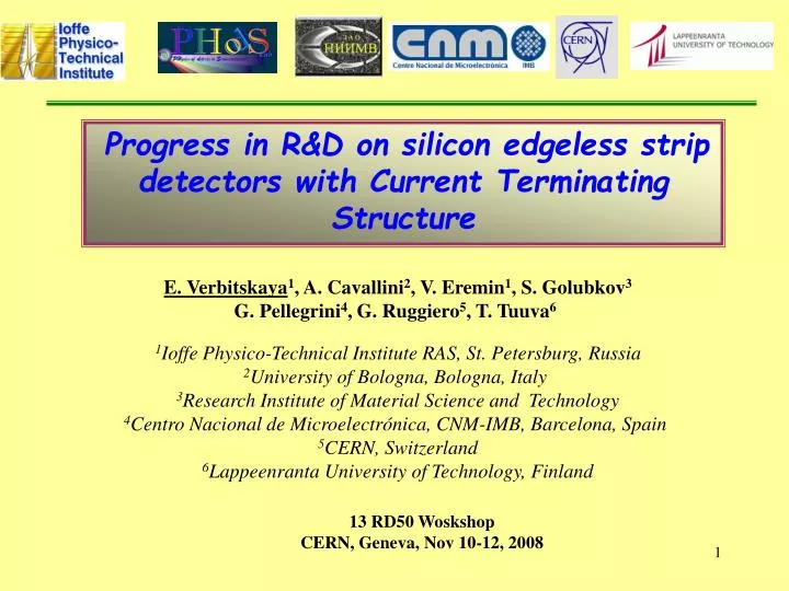
Progress in R&D on silicon edgeless strip detectors with Current Terminating Structure. E. Verbitskaya 1 , A. Cavallini 2 , V. Eremin 1 , S. Golubkov 3 G. Pellegrini 4 , G. Ruggiero 5 , T. Tuuva 6 1 Ioffe Physico-Technical Institute RAS, St. Petersburg, Russia

E N D
Progress in R&D on silicon edgeless strip detectors with Current Terminating Structure E. Verbitskaya1, A. Cavallini2, V. Eremin1, S. Golubkov3 G. Pellegrini4, G. Ruggiero5, T. Tuuva6 1Ioffe Physico-Technical Institute RAS, St. Petersburg, Russia 2University of Bologna, Bologna, Italy 3Research Institute of Material Science and Technology 4Centro Nacional de Microelectrónica, CNM-IMB, Barcelona, Spain 5CERN, Switzerland 6Lappeenranta University of Technology, Finland 13 RD50 Woskshop CERN, Geneva, Nov 10-12, 2008
Outline • Overview of the approaches for rad-hard edgeless detectors • Edgeless detector with CTS: design • Models forpotential and electric field distribution in p-on-n edgeless detector and experimental results • Simulation of irradiated detectors • Experimental results on CCE (test beam) • Development of n-on-p edgeless detectors • Conclusions E. Verbitskaya et al., 13 RD50 Workshop, CERN, Nov 10-12, 2008
Requirements Requirement: diminished dead area adjacent to detector sensitive area Close-to-beam applications (CERN, TOTEM, Roman pot) - maximal dead area width less than 50 µm Other applications: imaging tileable arrays for diagnostics (medicine, biology etc.) Solution: edgeless detectors (diced or cut) Problem: elimination of the influence of high current from damaged cut on the properties of detector sensitive bulk E. Verbitskaya et al., 13 RD50 Workshop, CERN, Nov 10-12, 2008
Prehistory Z. Li et al., IEEE Trans. Nucl. Sci. NS-49 (2002) 1040-1046 Pad detectors diced across p-n junction • I-V improvement: • Dicing from the back side • Aging at RT E. Verbitskaya et al., 13 RD50 Workshop, CERN, Nov 10-12, 2008
Strip - Overview of the approachesfor edgeless detectors Regular planar strip detector with Voltage Terminating Structure (VTS) E. Verbitskaya et al., 13 RD50 Workshop, CERN, Nov 10-12, 2008
Approach: Edgeless strip detectorwith Current Terminating Structure (CTS) Regular p+-n-n+ strip detector with Voltage Terminating Structure (VTS) TOTEM: Edgeless p+-n-n+strip detector with CTS Cut through p+ outer ring 1. G. Ruggiero et al. IEEE Trans. Nucl. Sci. 52 (2005) 1899. 2. E. Noschis et al. Nucl. Instr. and Meth. A 563 (2006) 41. E. Verbitskaya et al., 13 RD50 Workshop, CERN, Nov 10-12, 2008
Alternative approach:full 3D active edge detectors C. Da Via et al., NIM A587 (2008) 243-249 • Main features of design: • p+ and n+ through entire bulk • p+ active edge • collection distance ≤ 50 mm fast response higher electric field due to cylindrical geometry radiation hardness but • Complicated technology E. Verbitskaya et al., 13 RD50 Workshop, CERN, Nov 10-12, 2008
Further development of edgeless detectors with CTS: INTAS-CERN project TOSTER:TOtem STrip Edgeless Radiation hard detectors # 05-103-7533Started: July 2006 CONSORTIUM CERN - Switzerland Ioffe Physico-Technical Institute RAS - Russia Research Institute of Material Science and Technology - Russia Centro Nacional de Microelectronica - CSIC – Barcelona, Spain University of Bologna - Italy Lappeenranta University of Technology – Finland Head of the project: Gennaro Ruggiero (CERN) E. Verbitskaya et al., 13 RD50 Workshop, CERN, Nov 10-12, 2008
Current Terminating Structure (grounded) Clean-Up Ring (CUR) Current Terminating Ring (CTR) Sensitive area Non-sensitive corner Conceptual designof edgeless detector with CTS Voltage Terminating Rings (floating) The current of CTR: ohmic current along the damaged cut The current of CUR: diffusion current from the cut to the bulk The current of sensitive area: bulk generated current E. Verbitskaya et al., 13 RD50 Workshop, CERN, Nov 10-12, 2008
Performanceof edgeless detector with CTS Dead area 47 mm E. Verbitskaya et al., 13 RD50 Workshop, CERN, Nov 10-12, 2008
Electrical characteristicsof p-on-n edgeless detectors Statistics of reverse current Processed by Ioffe&RIMST I-V characteristics n-Si, r ~ 20 k·cm Vfd: ~20 V; S = 8 cm2 512 strips with a pitch of 66 µm V = 100 V Bulk current: Imean = 120 nA Jmean ~ 12 nA/cm2 Istrip = 20 pA E. Verbitskaya et al., 13 RD50 Workshop, CERN, Nov 10-12, 2008
Potential distribution on VTS rings in p-on-n detector before and after scribing After cut Before cut Test detectors Before the cut: potential distribution occurs via punch-though effect, and potentials between the rings are distributed linearly. After cut: potential distribution is controlled by the increased current across the damage surface (~mA). VTS operates and distributes potential outside the detector active area and eventually prevents the electric field focusing at the border of the detector active area. E. Verbitskaya et al., 13 RD50 Workshop, CERN, Nov 10-12, 2008
z p+ 0 Ez Exs Surface current Is Exb x n+ X Models of potential and electric field distribution at the sensitive cut Components of potential and electric field In x direction: Vxs, Exs Vxb, Exb at the cut (s) and inside the bulk (b) In z direction: Ez – normal to the cut Potential in the bulk Vxb ~ x2 Ez ≈ (Vsurf –Vbulk)/Wz Wz – distance at which Vxs dissipates to Vxb Exb ~ x E. Verbitskaya et al., 13 RD50 Workshop, CERN, Nov 10-12, 2008
Nd z Nd z x z 1. Model of resistive edge layer Damaged edge with high concentration of defect levels 1: Resistive layer: controls potential distribution Vxs(x) 2: Generation layer: electrons and holes are generated Free carriers in the generation layer do not disturb Is and Vxs E. Verbitskaya et al., 13 RD50 Workshop, CERN, Nov 10-12, 2008 E. Verbitskaya, RESMDD’08, Florence, Oct 15-17, 2008
p+ E(z) Ez Surface ohmic current n+ Potential at the cut Vxs Vxb X Vxs X X X Model of resistive edge layer Potential in the bulk Vxb Exb - linear Exb – const Generated carriers: holes move to CTS; electrons may partially flow inside the bulk E. Verbitskaya et al., 13 RD50 Workshop, CERN, Nov 10-12, 2008
z p+ 0 Ez Ie Exs Ih Exb I = Ie + Ih x n+ Ez Vx Vxb Vxs X X 2. Model of amorphous edge layer jh = gh(d - x) je = (ge – ηe )x g – generation rate ηe ↑ Inversion of Ez sign! – forces holes to move towards the bulk E. Verbitskaya et al., 13 RD50 Workshop, CERN, Nov 10-12, 2008
Tools for studyof potential and electric field distribution Simulation of potential, electric field and hole trajectories (Ioffe Institute) Conductive MicroProbe Technique (Bologna University) Scanning Transient Current Technique (Ioffe Institute) E(x) simulation usingISE-TCAD with implemented Poisson and continuity equations (CNM Barcelona) Additionally: Optical Beam Induced Current (Bologna Univ.) Scanning Electron Microscope (LUT) E. Verbitskaya et al., 13 RD50 Workshop, CERN, Nov 10-12, 2008
Simulations: potential and electric field distribution, resistive edge Neff = 31011 cm-3; Vfd = 15 V Ez ≈ (Vsurf –Vbulk)/Wz Wz = 300 mm E. Verbitskaya et al., 13 RD50 Workshop, CERN, Nov 10-12, 2008
Experimental results on MicroProbe Technique:surface potential SP(x), and E(x) at the cut edge -10 to -150 V Potential is nonlinear E(x) is not constant Slope of E(x) grows with voltage Main features: disagreement with resistive edge model E. Verbitskaya et al., 13 RD50 Workshop, CERN, Nov 10-12, 2008
Potential and Ez distributions based on CMPT data Ez sign inversion red: Vs (CMPT) blue: Vb Experimental results on surface potential are in agreement to the amorphous edge model E. Verbitskaya et al., 13 RD50 Workshop, CERN, Nov 10-12, 2008
Exs derived from STCT V = 100 V, Vfd = 20 V, d = 300 mm n+ p+ At V > Vfd Results on Ex(x) derived from CMPT and STCT show the same tendency of Es reduction E. Verbitskaya et al., 13 RD50 Workshop, CERN, Nov 10-12, 2008
Ez simulation in irradiated p-on-n edgeless detectors E. Verbitskaya, RESMDD’08, Florence, Oct 15-17, 2008
Ez simulation in irradiated p-on-n detectors V = 400 V F ↑ Ez is ~kV/cm and increases with fluence predicts the increase of the hole current flow into the bulk and corresponding increase of the bulk current. E. Verbitskaya et al., 13 RD50 Workshop, CERN, Nov 10-12, 2008
E(x) simulation using ISE-TCAD J.P. Balbuena et al., CNM, Barcelona, presented at NSS-2008 and are in progress CTR p-on-n detector, saw cut edge Electric field at the front contact is maximal at CTR (10 to 50 mm from the edge) and becomes lower under the strips E. Verbitskaya et al., 13 RD50 Workshop, CERN, Nov 10-12, 2008
Ez simulation in irradiated p-on-n detectors (preliminary) Fn = 4·1014 cm-2 Non-irradiated E. Verbitskaya et al., 13 RD50 Workshop, CERN, Nov 10-12, 2008
Recent experimental results on CCE in p-on-n edgeless detectors with CTS Efficiency of CTS detector at the sensitive edge The left-most vertical line indicates the reconstructed position of the physical edge, theother two vertical lines indicate the 10%-90% efficiency rise interval. Diminished non-sensitive width of 47 μm is achieved! G. Ruggiero et al. Planar Edgeless Silicon Detectors for the TOTEM Experiment. Pres. 8th Intern.Conf. on Position Sensitive Detectors (PSD8), Glasgow, Sept 1-5, 2008, Nucl. Instr. and Meth. A (in press). E. Verbitskaya et al., 13 RD50 Workshop, CERN, Nov 10-12, 2008
CCE in irradiated p-on-n edgeless detectors with CTS 24 GeV/c protons T = -18C The efficiency has been calculated by comparing the hits in the irradiated detector with the hits in a non-irradiated detector placed in front, along the beam axis. E. Verbitskaya et al., 13 RD50 Workshop, CERN, Nov 10-12, 2008
Development of n-on-p edgeless detectors with CTS Layout: 10 different designs MCZ p-type Si Processed by Ioffe&RIMST E. Verbitskaya et al., 13 RD50 Workshop, CERN, Nov 10-12, 2008
I-V characteristics of n-on-p edgeless detectors I-V characteristics Statistics of reverse current 14 randomly selected detectors with different design V = 200 V; S = 8x8 mm2 84 samples Jmean = 30 nA/cm2 10-30 nA MPT and TCT measurements are in progress! E. Verbitskaya et al., 13 RD50 Workshop, CERN, Nov 10-12, 2008
Conclusions Performance of edgeless detectors withCTS allows realization of edgeless detectors which characteristics are controlled by the bulk properties The model of amorphous edge is adequate to the experimental results on n-on-p edgeless detectors In detectors with CTS diminished non-sensitive width of 47 μm is achieved N-on-P edgeless strip detector seems to be radiation hard that needs experimental testing E. Verbitskaya et al., 13 RD50 Workshop, CERN, Nov 10-12, 2008
Acknowledgements • This work was done in the frame of INTAS-CERN project # 03-52-5744 • and supported in part by: • RF President Grant # 2951.2008.2, • contract of Russian Agency on Science and Innovation # 2.516.11.6098 Thank you for your attention! E. Verbitskaya et al., 13 RD50 Workshop, CERN, Nov 10-12, 2008