Download
1 / 14
140 likes | 313 Views
Magnetic measurement systems for future high performance magnets P Arpaia 1 , R Beltron, L Bottura, M Buzio , D Cote, G Deferne, O Dunkel, L Gaborit, J Garcia Perez, D Giloteaux, G Golluccio 1 , V Inglese 1 , G Montenero 1 , G Spiezia 1 , L Walckiers

E N D
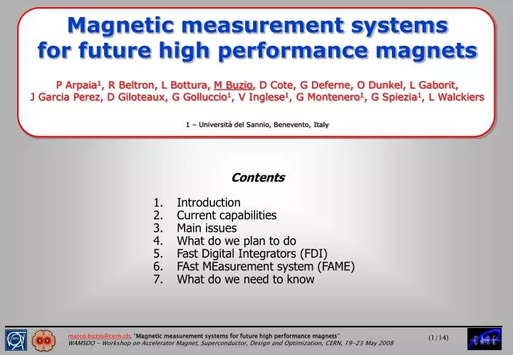
Magnetic measurement systems for future high performance magnets P Arpaia1, R Beltron, L Bottura, M Buzio, D Cote, G Deferne, O Dunkel, L Gaborit, J Garcia Perez, D Giloteaux, G Golluccio1, V Inglese1, G Montenero1, G Spiezia1, L Walckiers 1 – Università del Sannio, Benevento, Italy Contents • Introduction • Current capabilities • Main issues • What do we plan to do • Fast Digital Integrators (FDI) • FAst MEasurement system (FAME) • What do we need to know
Introduction • Magnetic measurement servicesat CERN centralized in two work units as of 2007:PH-DT1-MM: experimental magnetsAT-MEI-MM: accelerator magnets (resistive, superconducting … everything BUT kickers) • Accumulated equipment and knowledge from many groups and projects over 50 years • Most instruments optimized for a specific magnet family (LHC, SPS, etc ..)adaptations possible but not always practical • Large variety some duplication of functionality, costly maintenance, HW and SW platforms not always consistent (LabView, Visual Basic, C …) • Overall: an extensive array of instruments, devices and facilities that has served well its purpose for the existing machines • Present objectives • Qualify new/repaired magnets for existing machines and upgrades • Refine magnetic models for accelerator operation (“FIDEL”) • Extend capabilities and improve accuracy for LHC and future projects
Current status – instrumentation • Typical accuracies: B1 10-4, B2 10-3, harmonics (relative) 10-5, magnetic axis wr.t. external fiducials 0.2 mm • Instruments often customized for internal use and external collaborations eg CNAO, ASG, CELLS/ALBA, Saclay • Main HW platform: VFC-based “Programmable Digital Integrator” PDI on VME bus
Current status – measurement coils X-section of 20x20 multi-strand flat cable coil Inset quadrupole-compensated coil for Linac4 PMQs 2.5 m curved fluxmeter array for CNAO dipoles X-section of 15m long LHC ceramic coil shaft • Large stock (~1000) of measurements coils and assemblies (20 mm70 mm, 2 mmL7 m) • Specialized coil manufacturing and calibration facility: 2 mm to 2 m long, up to 4000 turns with mono- (machine wound) or multi-strand wire (manually wound), air or G10 core • Coil arrays, dipole and quadrupole-compensated assemblies (bucking factor up to 6000 with matched sets) on ceramic or composite supports, straight or curved • Specific expertise in design, micro-welding, precision machining, gluingand magnetic calibration
New demands Magnet parameters • Linac 4 • Resistive • Bpeak~1 T • Ḃ ~700 T/s (EMQ) • CYCLE 1.6~6.0 ms • CB 20~70 mm • LHC Upgrade Phase I • NbTi • Bpeak~10 T • CB 110~130 mm • LHC Upgrade Phase II • Nb3Sn • Bpeak 12~15 T • CB 130~150 mm • PS2 • NbTi • Bpeak ~1.8 T • Ḃ ~ 2 T/s • CB ~70 mm Measurement parameters • LHC (or any SC magnet): improve time resolution (0.15 Hz) and harmonic accuracy (0.10.02 units) for dynamic phenomena (snapback) • Fast-pulsed magnets: improve time resolution for local/integral eddy current transients (recently required for PS & CNAO) • Linac 4: measure magnetic axis in assembled DTL module (20 × 1500 mm bore) • LHC Upgrade: same accuracy of strength/harmonics/axis than existing triplets (??)
Main issues • Higher B + higher dB/dt+ larger = higher signal= better measurement, however … • Harmonic/fixed coil systems • Faster measurements and/or increased B, Ḃ, signals exceeding typical 10V range use coils with reduced surface (turns), modulate rotation speed (better accuracy) and/or amplifier gain (more practical) • Faster measurements continuous rotation • Existing PDI integrators cannot cope with high acquisition bandwidth • Larger BORE keep COIL ≳⅔BORE to minimize harmonic extrapolation errors design & build new coil support shafts • Larger COIL massive ceramic shafts unsuitable new mechanical design necessary(but: easier to machine, room to add optical targets for axis detection) • Larger COIL calibration in existing reference magnets may be not possible new reference magnets/calibration procedures/coil geometries • General problems • Eddy current magnetic forces scale as BḂ effects on probe materials increased by 101~102 • High field reference magnets: needed for sensor calibration, material and system characterization(NB: existing Metrolab NMR teslameter maxes at 14 T, primary reference needed)
What do we plan to do • Undergoing Activities • Higher speed signal acquisition and integration Fast Digital Integrator (FDI) • Higher speed harmonic measurements FAstMEasurementsystem (FAME) • Obsolescent software Flexible Framework for Magnetic Measurements (FFMM) (with UniSannio) • Linac 4 Existing Linac 2 bench being upgraded for permanent and fast-pulsed magnet(new mechanics, coils, integrators, power supplies, software) • Future Activities • Large diameter bores R&D for suitable coil shafts (geometry, materials, calibration etc..) • coil shaft for short models in vertical cryostat(“Bloc4” cold measurement system) • coil shaft for long cryoassemblies w/ anticryostat(SM18 test benches) • General-purpose travelling probe family with tangential harmonic coils and optical target for axis detection (“supermole”) • R&D on components at high B/Ḃ: inclinometers, piezo motors, encoders etc … • Measurement and analysis techniques for strongly curved magnets
PXI-3320 chassis PXI-8570 Encoder Board Coil signal Trigger signal Fast Digital Integrator (FDI) – overview • joint development since 2005 with Università del Sannio (Italy) • PXI board integrating analog front-end, programmable amplifier,18-bit ADC, DSP numerical processing • software drivers for LabView + new in-house C++ class framework (FFMM) Cables from PCI-8570(PC host) • aim: increase bandwidth and accuracy for fast fixed- and rotating-coil magnetic measurements • Set to replace existing base of VFC-based PDIs – workhorse of our future HW platform
Fast Digital Integrator (FDI) - characteristics • overvoltage-protected, low-pass filtered analog front-end • fast-switchable programmable gain levels from 0.1 to 100 • auto-calibration of gain & offset with Vreferencegenerator • 18-bit, 500 kHz ADC • DSP allows multiple upgradeable integration/filtering/compression algorithms • FPGA glues logically components • industry-standard compact PCI interface • real-time LED display of gain and signal level
Fast Digital Integrator (FDI) - performance • Main advantages in switching from PDIs to FDIs: • Integrated board(filter+ampli+ADC) higher noise rejection, streamlinedimplementation, more cost-effective • Bandwidth up to 250 kS/s(PDI: 1 kS/s) • Signal-to-noiseup to 110 dB(PDI: 70 dB) • Equivalent resolution: 0.5 nVs(PDI: 50 nVs) Signal-to-noise metrics:SINAD (Signal to Noise And Distortion Ratio)SNHR(Signal to Non Harmonic Ratio)THD(Total Harmonic Distortion) test carried out with pure sine wavesignal @ 10 Hz, 20 Vpptrigger rate = up to 256/revolution FDI v 0.2 performanceas a digitizer FDI v 0.1 PDI performanceas an integrator OSR = oversampling ratio = ADC sampling rate/encoder trigger rate (typical value: 2000)
Fast Digital Integrator (FDI) - outlook • 12 prototype cards in use, 40 in production (NB long lead times for components) • firmware and drivers being updated to exploit full HW capabilities (software programmable trigger generation, ADC mode, elimination of card-to-PCI bus bottleneck) • Possible future HW upgrades: stand-alone version with USB interface, increased buffer memory, 18-bit DAC for flexible self-calibration and programmable function generation; • commercialization accord with METROLAB in progress lower volume/maintenance costs !
FAME (FAst Measurement system) - overview • Continuous, high-speed (8 Hz) harmonic measurement system for main LHC dipoles and quadrupoles improvement of magnetic model for accelerator control (FIDEL) • High-accuracy, high bandwidth integrated and local field quality during snapback transients • Upgraded ceramic coil shaft with 6-turns coils, better mass balancing, robust connectors • Compact Mobile Rotating Unit (MRU) simplifies installation and maintenance, might be adapted to other rotating coil systems (downside: longitudinal positioning requires Ti extension pieces)
FAME – first results and outlook Comparison of center harmonics in warm LHC dipole with FAME/FDI and old (PDI) system NB: the two current cycles shown differ by pre-cycle duration, no cleansing quench in between results not directly comparable Qualitative comparison of center b3 snapback curves in LHC dipole with FAME/FDI and PDI system • Validation and characterization test campaign being carried out with two prototype MRU + dipole shafts in SM18(tests interrupted due to a cryogenic accident freezing the prototype shaft – now being repaired) • Results coincide with older system within measurement uncertainty (< 0.1 unit) • Coming next: spare dipole + quadrupole system; integration in new control/analysis software framework; new analysis algorithms to improve accuracy and bandwidth (harmonic reconstruction in rapidly changing field, progressive update during coil rotation)
What do we need and when ? • Timely input from our valued magnetic measurement clients ! • Critical information: • cold bore: some R&D required + long lead times for coil shafts (and anticryostats) • twist pitch: in long shafts, gap and coil length must be integer multiples of • Also important to know: • Maximum B and Ḃ • Geometrical parameters: good field region, magnet length, curvature radius for short dipoles, position of mechanical references/optical targets • Desired accuracy for field strength, harmonics, direction and axis • … have you got a magnet to spare ? • high field/large aperture magnets to be kept stably as references for calibration and cross-checks, and as test beds for materials and technologies